


FIGURE 6.49 Schematics of the basic Michelson interferometer.
They are reflected off of both the stationary and the translatable mirror whose displacement x is to be measured, and recombined at the splitter, where they are redirected toward a concave lens. Due to the coherence of the laser light, the wavefronts have a well-defined phase relation with respect to each other. This phase is determined by the difference between the optical path lengths of the two beams in arms 1 and 2. If this path difference is continuously changed by translating one of the mirrors, a sinusoidal intensity variation can be observed at a fixed location in space behind the lens used to introduce a beam divergence, resulting in an annular fringe pattern. The pinhole is used to define an exact location of observation and the photodetector picks up the varying intensity for further processing. In the most basic signal processing setup, the number of bright and dark cycles are fed into a counter, which then counts changes in optical path length in integer multiples of λA/2. More sophisticated signal processing not only counts cycles but also determines relative phase changes in the sinusoidal varying intensity so that resolutions of λA/512 can ultimately be achieved.
When moving the mirror, one must guarantee a smooth motion without backward jitter of the mirror carriage to avoid double counts of interference fringes. Very high-quality linear bearings (such as air bearings) are necessary to accomplish just that.
As can be seen in Figure 6.49, the light reflected off both mirrors essentially retraces its own path and is at least partially incident onto the active volume of the laser source (3), thereby forming an external laser resonator which is able to detune the laser, effectively modulating its output power as well as its wavelength. To avoid this effect, commercial versions of Michelson interferometers employ corner-cube reflectors instead of plane mirrors as well as optical isolators, as shown in Figures 6.50 and 6.51. Some authors, however, report using optical arrangements that utilize this effect in conjunction with laser diodes to realize low-cost, short-travel displacement sensors [18, 19]. These setups will not be discussed here, however.
Two-Frequency Heterodyne Interferometer
Figure 6.50 shows the commercially available two-frequency Michelson interferometer operating with a Zeeman-stabilized He–Ne laser source. This laser emits two longitudinal modes with frequencies f1 and f2 that are both circularly polarized in opposite directions. By passing the modes through a quarter-wave
© 1999 by CRC Press LLC
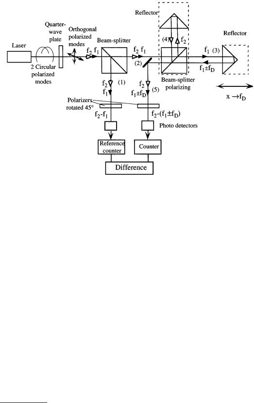
FIGURE 6.50 Two-frequency heterodyne interferometer (Courtesy of Spindler & Hoyer Inc.).
plate, two orthogonal linearly polarized waves are generated. Both are split by a nonpolarizing beam splitter. There is a polarizer located in arm 1 of that splitter, which is rotated by 45° with respect to both polarized waves impingng on it, thus effectively allowing them to interfere behind it yielding a difference frequency of f2 – f1 that is picked up by a photodetector and counted by a reference counter (frequency difference typically 1.5 MHz).
The orthogonal polarized waves in 2 are further split by a polarizing splitter. Spectral component f1 < f2 is transmitted into measuring arm 3 and frequency component f2 is reflected into reference arm 4 of the interferometer. Due to the velocity v of the reflector in arm 3 resulting in a displacement x, the frequency f1 is Doppler-shifted by fD (Equation 6.74). Movement of the reflector toward the interferometer results in a positive Doppler frequency fD > 0. After recombining both waves from 3 and 4 in the beam splitter again, they are sent through a polarizer in arm 5 that also is rotated by 45° with respect to the direction of polarization of both recombined waves, thereby allowing them to interfere, yielding a difference frequency of f2 – f1 – fD at the location of the photodetector, which is counted by a second counter. By continuously forming the difference of both counts, the measurand (the displacement of x in multiples of λA/2) is calculated.
With this type of interferometer, the direction of motion is given by the sign of the resulting count. One disadvantage of the two-mode heterodyne interferometer is its limited dynamic range for the velocity v of the reflector moving toward the interferometer, since the Doppler frequency fD , given by:
f = |
2 |
v |
(6.74) |
|
|||
D |
λA |
|
|
|
|
|
|
is bound to be less than the initial frequency difference between f2 and f1 for stationary reflectors. Given a typical Zeeman effect-induced frequency difference fz of 1.5 MHz, the velocity v is therefore bound to be less than:
© 1999 by CRC Press LLC
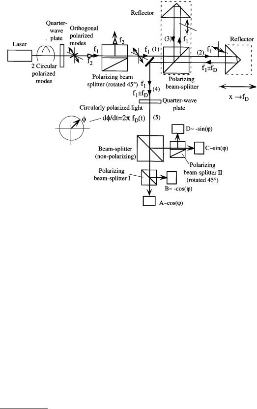
FIGURE 6.51 Single-mode homodyne interferometer (Courtesy of Spindler & Hoyer Inc.).
v < |
fz |
λ |
A |
= 0.474 m s-1 |
(6.75) |
|
|||||
2 |
|
|
|
||
|
|
|
|
||
There is no such bound if the reflector is traveling away from the interferometer. By electronically interpolating the output signal of the photodetector, subwavelength resolution can be obtained [22].
Single-Mode Homodyne Interferometer
An interferometer setup that has no limitation on the maximum velocity in the above sense is the singlemode homodyne interferometer shown in Figure 6.51.
As in the two-frequency heterodyne interferometer, a Zeeman effect-stabilized laser source that emits two frequency-displaced circularly polarized axial modes is usually used. After passing through a quarterwave plate, two orthogonal polarized waves are generated, only one of which (f1) is further used. The other (f2) is reflected out of the optical path by an appropriately oriented polarizing beam splitter. The plane of polarization in arm 1 of the interferometer is tilted by 45° with respect to the plane defined by the two arms 2 and 3. The second polarizing beam splitter will transmit one horizontally oriented component into the measuring arm 2 and reflect a vertically oriented component into the reference arm 3 of the interferometer. The two arms of the interferometer maintain their orthogonal polarizations. The frequency of the wavefront in arm 2 is shifted by the Doppler effect (Equation 6.74) due to the motion of the reflector. The light reflected by the two triple mirrors is recombined in the polarizing beam splitter and redirected by a mirror. Since in this particular optical setup, the polarization states of the two beams in the two arms of the interferometer are orthogonal, there is no interference after the redirecting mirror
© 1999 by CRC Press LLC

in arm 4 as was the case with the basic Michelson interferometer setup (Figure 6.49). After passing a quarter-wave plate at 45°, two opposite circular polarized waves (one with frequency f1, the other with frequency f1 ± fD) are generated and can be described by a rotating phasor (characterized by Φ(t)) with constant amplitude whose rate of rotation is dependent on the Doppler frequency (in arm 5). Amplitude fluctuations can be observed at the photodetectors A–D after this phasor has passed polarizers, which it does after being split by a nonpolarizing beam splitter.
The output of an interferometer has the general form:
I(t ) = Io (t ) |
1 |
é1+ cos(F(t ))ù |
(6.76) |
|
|
||||
2 |
ê |
ú |
|
|
ë |
û |
|
||
It is desired to infer Φ(t) from observation of I(t). Note that Io(t), which is the intensity of the laser, can also fluctuate with time. The problems encountered with this are (1) the ambiguity in the sign of Φ(t) and (2) the dependence of the calculated phase on the intensity fluctuations due to the aging of the laser and optical components. The first problem stems from the fact that arccos(…) yields two solutions to Equation 6.76:
F(t ) = ±arccos |
êé |
2I(t ) |
úù |
(6.77) |
||
ê I |
|
(t ) |
- 1ú |
|||
|
ë |
|
o |
|
û |
|
The sign ambiguity can be resolved by also generating a sin(Φ(t)) yielding quadrature signals. In order to do so, a second output of the interferometer of the form:
I2 (t ) = Io (t ) |
1 |
é1 |
+ sin (F(t ))ù |
(6.78) |
|
||||
2 |
ê |
ú |
|
|
ë |
û |
|
||
is sought. Equations 6.76 and 6.78 will determine Φ(t) unambiguously only in the region [0,2π), but there is still an ambiguity modulo 2π. The second problem can be dealt with by adding two more outputs of the form:
I3(t ) = Io (t ) |
1 |
|
é1 |
- cos (F(t ))ù |
(6.79) |
|
|
|
|||||
2 |
|
ê |
ú |
|
||
|
ë |
û |
|
|||
I4 (t ) = Io (t ) |
1 |
é1 |
- sin (F(t ))ù |
(6.80) |
||
|
||||||
2 |
ê |
ú |
|
|||
ë |
û |
|
||||
Taking Equations 6.76 to 6.79 and 6.78 to 6.80, it is possible to obtain a zero crossing at the linear most sensitive point of inflection of the fringe where the effect of intensity fluctuations on the phase measurement is minimal. The setup of Figure 6.51 attempts to obtain these four outputs. Signal A represents the intensity variations as given in Equation 6.76 and signal B due to the nature of the splitting action is shifted with respect to A by 180° (Equation 6.79). There is another arm to the right of the nonpolarizing beam splitter incorporating the polarizing beam splitter II, which is rotated by 45° with respect to beam splitter I so that the attached detectors C and D are generating the signals defined by Equations 6.78 and 6.80.
Since the Doppler frequency is time dependent according to the velocity v of the measuring reflector, the distance, x, traveled by the reflector up to time T is given by Equation 6.81.
|
T |
T |
lA |
|
T ¶F(t ) lA |
|
||
x = ò0 |
v(t ) dt = ò0 |
fD (t ) |
|
dt = ò0 |
|
|
4p dt |
(6.81) |
2 |
|
¶t |
||||||
© 1999 by CRC Press LLC
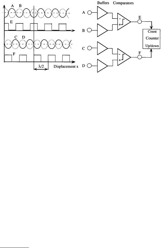
FIGURE 6.52 A simple signal conditioning circuit yielding quadrature signals E and F.
It should be noted that the resolution of this interferometer is limited to λA/4 if no special hardware is used to interpolate between interference fringes.
This particular interferometer is not limited with respect to a maximum unambiguous Doppler frequency.
Interferometer Signal Processing
At the photodetectors ends the optical path of the interferometers. Since the photodetectors are sensitive to light intensity values only the sinusoidal signal caused by motion of the reflector will be superimposed onto a pedestal signal proportional to the mean intensity over time or displacement, respectively. The electronics attached to the photodetectors is aimed to reliably detect zero-crossings of the sinusoidal component of the signals (A through D) even under low contrast conditions by subtracting out the pedestal signal component in the comparators. Low fringe contrast can be the result of small reflector tilt and/or vibration during periods of reflector movement, nonideal interferometer alignment, and imperfections in optical components like unequal splitting of the beam in beam splitters. Figure 6.52 shows a simple conditioning unit.
The main purpose of that set up is to produce digital quadrature signals (E and F in Figure 6.52) that can most easily be used to perform signal interpolation digitally [20, 21] and also allow for the determination of the direction of movement by using, for example, signal E as count signal and F as an up/down indicator.
Both comparators compare sinusoidal components having a possibly slowly time-varying dc pedestal amplified by buffer amplifiers. All photodetector signals A through D will be affected by this dc pedestal so that forming their difference in the comparator will yield zero-crossing signals independent of the pedestal. The two comparator units are necessary to generate quadrature signals for direction detection. Furthermore, this electronics allows easily for a fringe interpolation by a factor of 4, bringing the leastcount resolution of the interferometer down to ≈160 nm. This interpolation can be done if instead of feeding the signal E into the count input, the exored signal E F is used. In this case, the up/down terminal of the counter circuit needs to be connected to the signal E&F. If an even higher resolution is sought, digital interpolation of these quadrature signals can be performed [20–22].
Conclusions
Using laser interferometers operating with highly stabilized laser sources, relative uncertainties in length measurements as low as 5 × 10⁻⁸ can be realized, which makes these kinds of equipment suitable to convey
© 1999 by CRC Press LLC

primary and secondary length standards into industrial measurement labs. Since, for practical purposes, these interferometers need to be operated in ambient air, the uncertainty in the refractive index of air gives the largest single factor limiting the overall precision. Decreasing the uncertainty stemming from that source necessitates the determination of environmental parameters such as relative humidity, temperature along the optical path, and atmospheric pressure with very little error. Laser refractometers able to determine the refractive index of air directly, on the other hand, allow for the direct measurement and compensation of the refractive index. Zeeman effect-stabilized laser sources can reach a relative uncertainty of less than 10–8 and thus contribute only a small portion of the overall error. The interferometer itself, depending on the signal processing involved, will have at least count resolution of λA/4 without any optical or electronic interpolation and can have an order of magnitude less uncertainty if highperformance phase meters are used to subdivide the wavelength λA. Very high-quality air bearings and a very well-controlled measurement environment are necessary to reach these goals.
Defining Terms
Heterodyne technique: The superposition of two harmonic signals with frequencies f1 and f2 in a nonlinear device results in a signal containing both sum and differences frequencies. For interferometric purposes where each individual frequency is in the 1014 Hz range, the frequency difference might be low enough to be registered by photodetectors. They also serve as nonlinear devices because their response is to light intensity only, which is proportional to the light amplitude squared.
Interference: A phenomenon that strikingly illustrates the wave nature of light. It occurs when radiation follows more than one path from its source to the point of detection. It may be described as the local departures of the resultant intensity from the law of addition as the point of detection is moved, for the intensity oscillates about the sum of the separate intensities.
Laser: The acronym of Light Amplification by Stimulated Emission of Radiation. It was originally used to describe light amplification, but has more recently come to mean an optical oscillator.
Refractive index: A number specifying the ratio of the propagation velocities of light in vacuum c to that in a medium. The refractive index for any medium is always somewhat larger than 1. Its value is dependent on the composition of the medium and the wavelength of the incident radiation.
Zeeman effect: An effect that is observed if excited atoms emit their radiation in the presence of a magnetic field. The longitudinal Zeeman effect causes a single emission line to split symmetrically into right and left circularly polarized lines.
References
1.Documents concerning the new definition of the metre, Metrologia, 19, 163-177, 1984.
2.E. Jaatinen and N. Brown, A simple external iodine stabilizer applied to 633 nm 612 nm and 543 nm He–Ne lasers, Metrologia, 32, 95-101, 1995.
3.A. E. Siegman, Lasers, Mill Valley, CA: University Science Books, 1986.
4.W. R. Steel, Interferometry, 2nd ed., (Cambridge studies in modern optics), Cambridge, U.K.: Cambridge University Press, 1985.
5.W. R. C. Rowley, The performance of a longitudinal Zeeman-stabilized He–Ne laser (633 nm) with thermal modulation and control, Meas. Sci. Technol., 1, 348-351, 1990.
6.Wolfgang Demtröder, Laser Spectroscopy: Basic Concepts and Instrumentation, 2nd ed., Berlin: Springer, 1996.
7.B. Edlén, The dispersion of standard air, J. Opt. Soc. Amer., 43(5), 339-344, 1953.
8.B. Edlén, The refractive index of air, Metrologia, 2(2), 71-80, 1966.
9.J. C. Owens, Optical refractive index of air: dependence on pressure, temperature and composition, Appl. Optics, 6(1), 51-59, 1967.
10.H. D. Baehr, Thermodynamik, 6th ed., Berlin: Springer, 1988.
©1999 by CRC Press LLC

11.R. Revelle, Carbon dioxide and world climate, Sci. Amer., 247(2), 35, 1982.
12.K. P. Birch, F. Reinboth, R. W. Ward, and G. Wilkening, Evaluation of the effect of variations in the refractive index of air upon the uncertainty of industrial length measurement, Metrologia, 30(1), 7-14, 1993.
13.K. P. Birch and M. J. Downs, An updated Edlén equation for the refractive index of air, Metrologia, 30, 155-162, 1993.
14.K. P. Birch and M. J. Downs, Corrections to the updated Edlén equation for the refractive index of air, Metrologia, 31, 315-316, 1994.
15.P. E. Ciddor, Refractive index of air: new equations for the visible and near infrared, Appl. Optics, 35(9), 1566-1573, 1996.
16.F. E. Jones, The refractivity of air, J. National Bureau of Standards, 86(1), 27-32, 1981.
17.W. T. Estler, High-accuracy displacement interferometry in air, J. Appl. Optics, 24(6), 808-815, 1985.
18.J. A. Smith, U. W. Rathe, and C. P. Burger, Lasers with optical feedback as displacement sensors, Opt. Eng., 34(9), 2802-2810, 1995.
19.N. Takahashi, S. Kakuma, and R. Ohaba, Active heterodyne interferometric displacement measurement using optical feedback effects of laser diodes, Opt. Eng., 35, 802-907, 1996.
20.K. Oka, M. Tsukada, and Y. Ohtsuka, Real-time phase demodulator for optical heterodyne detection processes, Meas. Sci. Technol., 2, 106-110, 1991.
21.J. Waller, X. H. Shi, N. C. Altoveros, J. Howard, B. D. Blackwell, and G. B. Warr, Digital interface for quadrature demodulation of interferometer signals, Rev. Sci. Instrum., 66, 1171-1174, 1995.
22.J. A. Smith and C. P. Burger, Digital phase demodulation in heterodyne sensors, Opt. Eng., 34, 2793-2801, 1995.
Appendix to Section 6.5
In the appendix below some companies are listed that manufacture either complete interferometer systems or major components thereof, such as beam splitters, retroreflectors, refractometers, wavemeters, etc. This list is by no means exhaustive. Furthermore, no price information is included because the system cost is too much dependent on the particular choice of system components.
Companies that produce interferometers or significant components.
|
|
Complete |
|
|
Complete |
Manufacturer |
Sub-systems |
systems |
Manufacturer |
Sub-systems |
systems |
|
|
|
|
|
|
Aerotech Inc. |
* |
* |
Oriel Instruments Inc. |
— |
* |
101 Zeta Drive |
|
|
250 Long Beach Blvd. |
|
|
Pittsburgh, PA 15238 |
|
|
Stratford, CT 06497-0872 |
|
|
Tel: (412) 963-7470 |
|
|
Tel: (203) 380-4364 |
|
|
Burleigh Inc. |
— |
* |
Polytec PI Inc. |
* |
* |
Burleigh Park |
|
|
Auburn, MA 01501 |
|
|
Fishers, NY 14453-0755 |
|
|
Tel: (508) 832-3456 |
|
|
Tel: (716) 924-9355 |
|
|
Spindler & Hoyer Inc. |
* |
* |
Hewlett-Packard Inc. |
* |
— |
459 Fortune Blvd. |
|
|
Test & Measurement |
|
|
Milford, MA 01757-1745 |
|
|
Customer Business Center, |
|
|
Tel: (508) 478-6200 |
|
|
P.O. Box 4026 |
|
|
Zygo Corporation |
* |
* |
Englewood, CO 80155-4026 |
|
|
Middlefield, CT 06455-0448 |
|
|
Tel: (800) 829-4444 |
|
|
Tel: (860) 347-8506 |
|
|
Melles Griot Inc. |
* |
* |
|
|
|
4665 Nautilus Court South |
|
|
|
|
|
Boulder, CO 80301 |
|
|
|
|
|
Tel: (303) 581-0337 |
|
|
|
|
|
|
|
|
|
|
|
© 1999 by CRC Press LLC