


3.UniMeasure, Inc., Position & Velocity Transducers, UniMeasure document No. 400113-27A, Corvallis, OR.
4.Instrument Society of America (Research Triangle Park, NC), ISA-S37.12-1977 (R1982) Specifications and Tests for Potentiometric Displacement Transducers, 1982.
5.E. C. Jordan (Ed.), Reference Data for Engineers: Radio, Electronics, Computer, and Communications,
7th ed., Indianapolis: H.W. Sams, 1985, 5–16.
6.D. C. Greenwood, Manual of Electromechanical Devices, New York: McGraw-Hill, 1965, 297–299.
7.E. S. Charkey, Electromechanical System Components, New York: Wiley-Interscience, 1972, 302–303.
8.Variable Resistive Components Institute (Vista, CA), VRCI-P-100A Standard for Wirewound and Nonwirewound Precision Potentiometers, 1988.
9.Timber-Top, Inc., P.O. Box 517, Watertown, CT 06795, Tel: (860)-274-6706; Fax (860)-274-8041.
10.J. Angeles and C. S. López-Cajún, Optimization of Cam Mechanisms, Dordrecht, The Netherlands: Kluwer Academic, 1991.
11.P. W. Jensen, Classical and Modern Mechanisms for Engineers and Inventors, New York: Marcel Dekker, 1991.
12.A. H. Slocum, Precision Machine Design, Englewood Cliffs, NJ: Prentice Hall, 1992.
13.Spectra Symbol Inc., data sheet: SoftPot® (Membrane Potentiometer), Salt Lake City, UT, 1996.
14.Dallas Semiconductor Corp., Digital Potentiometer Overview, web page: www.dalsemi.com/ Prod_info/Dig_Pots/, December 1997.
15.Midori America Corp., (Fullerton, CA) Midori Position Sensors 1995 Catalog.
6.2Inductive Displacement Sensors
Halit Eren
Inductive sensors are widely used in industry in many diverse applications. They are robust and compact, and are less affected by environmental factors (e.g., humidity, dust) in comparison to their capacitive counterparts.
Inductive sensors are primarily based on the principles of magnetic circuits. They can be classified as self-generating or passive. The self-generating types utilize an electrical generator principle; that is, when there is a relative motion between a conductor and a magnetic field, a voltage is induced in the conductor. Or, a varying magnetic field linking a stationary conductor produces voltage in the conductor. In instrumentation applications, the magnetic field may be varying with some frequency and the conductor may also be moving at the same time. In inductive sensors, the relative motion between field and conductor is supplied by changes in the measurand, usually by means of some mechanical motion. On the other hand, the passive transducer requires an external source of power. In this case, the action of the transducer is simply the modulation of the excitation signal.
For the explanation of the basic principles of inductive sensors, a simple magnetic circuit is shown in Figure 6.7. The magnetic circuit consists of a core, made from a ferromagnetic materia,l with a coil of n number of turns wound on it. The coil acts as a source of magnetomotive force (mmf) which drives the flux Φ through the magnetic circuit. If one assumes that the air gap is zero, the equation for the magnetic circuit can be expressed as:
mmf = Flux × Reluctance = Φ × A - turns |
(6.2) |
such that the reluctance limits the flux in a magnetic circuit just as resistance limits the current in an electric circuit. By writing the mmf in terms of current, the magnetic flux may be expressed as:
Φ = ni weber |
(6.3) |
In Figure 6.7, the flux linking a single turn is by Equation 6.3; but the total flux linking by the entire n number of the turns of the coil is
© 1999 by CRC Press LLC
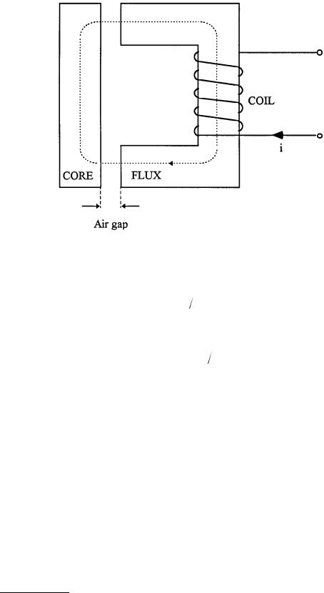
FIGURE 6.7 A basic inductive sensor consists of a magnetic circuit made from a ferromagnetic core with a coil wound on it. The coil acts as a source of magnetomotive force (mmf) that drives the flux through the magnetic circuit and the air gap. The presence of the air gap causes a large increase in circuit reluctance and a corresponding decrease in the flux. Hence, a small variation in the air gap results in a measurable change in inductance.
Ψ = nΦ = n2 i weber |
(6.4) |
Equation 6.4 leads to self inductance L of the coil, which is described as the total flux (Ψ weber) per unit current for that particular coil; that is
L = Ψ I = n2 |
(6.5) |
This indicates that the self inductance of an inductive element can be calculated by magnetic circuit properties. Expressing in terms of dimensions as:
|
= l μμ0 A |
(6.6) |
where l |
= the total length of the flux path |
|
µ |
= the relative permeability of the magnetic circuit material |
|
µ0 |
= the permeability of free space (= 4π × 10–7 H/m) |
|
A |
= the cross-sectional area of the flux path |
|
The arrangement illustrated in Figure 6.7 becomes a basic inductive sensor if the air gap is allowed to vary. In this case, the ferromagnetic core is separated into two parts by the air gap. The total reluctance of the circuit now is the addition of the reluctance of core and the reluctance of air gap. The relative permeability of air is close to unity, and the relative permeability of the ferromagnetic material is of the order of a few thousand, indicating that the presence of the air gap causes a large increase in circuit reluctance and a corresponding decrease in the flux. Hence, a small variation in the air gap causes a measurable change in inductance. Most of the inductive transducers are based on these principles and are discussed below in greater detail.
© 1999 by CRC Press LLC

FIGURE 6.8 A typical single-coil, variable-reluctance displacement sensor. The sensor consists of three elements: a ferromagnetic core in the shape of a semicircular ring, a variable air gap, and a ferromagnetic plate. The reluctance of the coil is dependent on the single variable. The reluctance increases nonlinearly with increasing gap.
Linear and Rotary Variable-Reluctance Transducer
The variable-reluctance transducers are based on change in the reluctance of a magnetic flux path. This type of transducer finds application particularly in acceleration measurements. However, they can be constructed to be suitable for sensing displacements as well as velocities. They come in many different forms, as described below.
The Single-Coil Linear Variable-Reluctance Sensor
A typical single-coil variable-reluctance displacement sensor is illustrated in Figure 6.8. The sensor consists of three elements: a ferromagnetic core in the shape of a semicircular ring, a variable air gap, and a ferromagnetic plate. The total reluctance of the magnetic circuit is the sum of the individual reluctances:
T = C + G + A |
(6.7) |
where C, G, and A are the reluctances of the core, air gap, and armature, respectively.
Each one of these reluctances can be determined by using the properties of materials involved, as in Equation 6.6. In this particular case, the reluctance T can be approximated as:
|
T |
= R μ |
C |
μ |
0 |
r2 |
+ 2d μ |
0 |
πr2 |
+ R μ |
A |
μ |
0 |
rt |
(6.8) |
|
|
|
|
|
|
|
|
|
|
© 1999 by CRC Press LLC

In obtaining Equation 6.8, the length of flux path in the core is taken as πR. The cross-sectional area is assumed to be uniform, with a value of πr2. The total length of the flux path in air is 2d, and it is assumed that there is no fringing or bending of the flux through the air gap, such that the cross-sectional area of the flux path in air will be close to that of the cross section of the core. The length of an average central flux path in the armature is 2R. The calculation of the appropriate cross section area of the armature is difficult, but it may be approximated to 2rt, where t is the thickness of the armature.
In Equation 6.8 all of the parameters are fixed except for the one independent variable — the air gap. Hence, it can be simplified as:
T = 0 + kd |
(6.9) |
where 0 = R/µ0 r [1/µCr +1/µAt], and k = 2/µ0 πr2
Using Equations 6.5 and 6.9, the inductance can be written as:
L = n2 ( |
0 |
+ kd) = L |
(1+ αd) |
(6.10) |
|
0 |
|
|
where L0 = the inductance at zero air gap α = k/ 0
The values of L0 and α can be determined mathematically: they depend on the core geometry, permeability, etc., as explained above. It can be seen from Equation 6.10 that the relationship between L and α is nonlinear. Despite this nonlinearity, these types of single coil sensors find applications in some areas, such as force measurements and telemetry. In force measurements, the resultant change in inductance can be made to be a measure of the magnitude of the applied force. The coil usually forms one of the components of an LC oscillator, for which the output frequency varies with the applied force. Hence, the coil modulates the frequency of the local oscillator.
The Variable-Differential Reluctance Sensor
The problem of the nonlinearity can be overcome by modifying the single coil system into a variabledifferential reluctance sensor (also known as push-pull sensor), as shown in Figure 6.9. This sensor consists of an armature moving between two identical cores, and separated by a fixed distance of 2d. Now, Equation 6.10 can be written for both coils as:
L1 = L01 [1+ α(d − x)],
(6.11)
L2 = L02 [1+ α(d + x)]
Although the relationship between L1 and L2 is still nonlinear, the sensor can be incorporated into an ac deflection bridge to give a linear output for small movements. The hysteresis errors of these transducers are almost entirely limited to the mechanical components. These sensors respond to both static and dynamic measurements. They have continuous resolution and high outputs, but they may give erratic performance in response to external magnetic fields. A typical sensor of this type has an input span of 1 cm, a coil inductance of 25 mH, and a coil resistance of 75 Ω. The resistance of the coil must be carefully considered when designing oscillator circuits. The maximum nonlinearity is 0.5%.
A typical commercially available variable differential sensor is shown in Figure 6.10. The iron core is located halfway between the two E-shaped frames. The flux generated by primary coils depends on the reluctance of the magnetic path, the main reluctance being the air gap. Any motion of the core increases the air gap on one side and decreases it on the other side, thus causing reluctance to change, in accordance
© 1999 by CRC Press LLC