


6.6 Bore Gaging Displacement Sensors
Viktor P. Astakhov
Dimensions are a part of the total specification assigned to parts designed by engineering. However, the engineer in industry is constantly faced with the fact that no two objects in the material world can ever be made exactly the same. The small variations that occur in repetitive production must be considered in the design. To inform the workman how much variation from exact size is permissible, the designer uses a tolerance or limit dimension technique. A tolerance is defined as the total permissible variation of size, or the difference between the limits of size. Limit dimensions are the maximum and minimum permissible dimensions. Proper tolerancing practice ensures that the finished product functions in its intended manner and operates for its expected life.
Bore Tolerancing
All bore dimensions applied to the drawing, except those specifically labeled as basic, gage, reference, maximum, or minimum, will have an exact tolerance, either applied directly to the dimension or indicated by means of general tolerance notes. For any directly tolerated decimal dimension, the tolerance has the same number of decimal places as the decimal portion of the dimension.
Engineering tolerances may broadly be divided into three groups: (1) size tolerances assigned to dimensions such as length, diameter, and angle; (2) geometric tolerances used to control a hole shape in the longitudinal and transverse directions; and (3) positional tolerances used to control the relative position of mating features. Interested readers may refer to [1, 2].
The ISO system of limits and fits (ISO Recommendation R 286) covers standard tolerances and deviations for sizes up to 3150 mm. The system is based on a series of tolerances graded to suit all classes of work from the finest to the most coarse, along with different types of fits that range from coarse clearance to heavy interference. Here, fit is the general term used to signify the range of tightness that may result from the application of a specific combination of tolerances in the design of mating parts.
There are 18 tolerance grades intended to meet the requirements of different classes of parts. These tolerance grades are referred to as ITs and range from IT 01, IT 02 (reserved for the future), and IT 1, to IT 16 (for today’s use). In each grade, the tolerance values increase with size according to a formula that relates the value of a given constant to the mean diameter of a particular size range. The system provides 27 different fundamental deviations for sizes up to and including 500 mm, and 14 for larger sizes to give different type of fits ranging from coarse clearance to heavy interference. Interested readers may refer to [3].
Bore Gage Classification and Specification
To measure the above-listed tolerances, modern manufacturing requires the use of gages. A gage is defined as a device for investigating the dimensional fitness of a part for specific function. Gaging is defined by ANSI as a process of measuring manufactured materials to assure the specified uniformity of size and contour required by industries. Gaging thereby assures the proper functioning and interchangeability of parts; that is, one part will fit in the same place as any similar part and perform the same function, whether the part is for the original assembly or replacement in service.
Bore gages may by classified as follows:
1.Master gages
2.Inspection gages
3.Manufacturer’s gages
4.Gages that control dimensions
5.Gages that control various parameters of bore geometry
6.Fixed limit working gages
© 1999 by CRC Press LLC

7.Variable indicating gages
8.Post-process gages
9.In-process gages
Master gages are made to their basic dimensions as accurately as possible and are used for reference, such as for checking or setting inspection of manufacturer’s gages. Inspection gages are used by inspectors to check the manufactured products. Manufacturer’s gages are used for inspection of parts during production.
Post-process gages are used for inspecting parts after being manufactured. Basically, this kind of gage accomplishes two things: (1) it controls the dimensions of a product within the prescribed limitations, and (2) it segregates or rejects products that are outside these limits. Post-process gaging with feedback is a technique to improve part accuracy by using the results of part inspection to compensate for repeatable errors in the machine tool path. The process is normally applied to CNC (computer numerically controlled) machines using inspection data to modify the part program, and on tracer machines using the same data to modify the part template.
In-process gages are used for inspecting parts during the machining cycle. In today’s manufacturing strategy, in-process gages and data-collection software provide faster feedback on quality. Indeed, the data-collection and distribution aspect of 100% inspection has become as important as the gaging technology itself. Software specifically designed to capture information from multiple gages, measure dozens of products types and sizes, and make it available to both roving inspectors and supervising quality personnel as needed, is quickly becoming part of quality control strategies. In conjunction with computer numerically controlled (CNC) units, in-process gaging can automatically compensate for workpiece misalignment, tool length variations, and errors due to tool wear.
Gages That Control Dimensions
Gages that control dimensions are used to control bore diameter. These gages can be either post-process or in-process gages. Further, these gages can be either fixed limit gages or variable indicating gages.
A plug gage is a fixed limit working bore gage. These inexpensive gages do not actually measure dimensions or geometry. They simply tell the operator whether the bore is oversized or undersized. The actual design of most plug gages is standard, being covered by American Gage Design (AGD) standards. However, there are many cases where a special plug gage must be designed.
A plug gage is usually made up of two members. One member is called the go end, and the other the no-go or not-go end. The gage commonly has two parts: the gaging member, and a handle with the sign, go or no-go, and the gagemaker’s tolerance marked on it. There are generally three types of AGD standard plug gages. First is the single-end plug gage (Figure 6.53(a)); the second is the double-end (Figure 6.53(b)); and the third is the progressive gage (Figure 6.53(c)). Interested readers may refer to [4].
Fixed-limit gage tolerance is generally determined from the amount of workpiece tolerance. A 10% rule is generally used for determining the amount of gage tolerance for fixed, limit-type gages. Four classes of gagemakers’ tolerances have been established by the American Gage Design Committee and are in general use [4]. These four classes establish maximum variation for any designed gage size. The degree of accuracy needed determines the class of gage to be used. Table 6.11 shows these four classes of gagemakers’ tolerances. Referring to Table 6.11, class XX gages are used primarily as master gages and for final close tolerance inspection. Class X gages are used for some types of master gage work and as close tolerance inspection and working gages. Class Y gages are used as inspection and working gages. Class Z are used as working gages where part tolerances are large. Table 6.12 shows the diameter ranges and prices of the plug gages manufactured by the Flexbar Machine Corp.
Variable indicating gages allow the user to inspect some bore parameters and get numbers for charting and statistical process control (commonly abbreviated as SPC). These gages have one primary advantage over fixed gages: they show how much a hole is oversized or undersized. When using a variable indicating gage, a master ring gage to the nominal dimension to be checked must be used to preset the gage to zero. Then, in applying the gage, the variation from zero is read from the dial scale. Figure 6.54 shows industry’s
© 1999 by CRC Press LLC
FIGURE 6.53 AGD cylindrical plug gages to inspect the diameter of holes: (a) two separate gage members; (b) two gage members mounted on single handle with one gage member on each end; (c) progressive gage.
TABLE 6.11 Standard Gagemakers’ Tolerances
|
To and |
|
Class |
|
|
|
|
|
|
|
|
Above |
including |
XX |
X |
Y |
Z |
|
|
|
|
|
|
0.010 in. |
0.825 in. |
0.00002 in. |
0.00004 in. |
0.00007 in. |
0.00010 in. |
0.254 mm |
20.95 mm |
0.00051 mm |
0.00102 mm |
0.00178 mm |
0.00254 mm |
0.825 in. |
1.510 in. |
0.00003 in. |
0.00006 in. |
0.00009 in. |
0.00012 in. |
20.95 mm |
38.35 mm |
0.00076 mm |
0.00152 mm |
0.00229 mm |
0.00305 mm |
1.510 in. |
2.510 in. |
0.00004 in. |
0.00008 in. |
0.00012 in. |
0.00016 in. |
38.35 mm |
63.75 mm |
0.00102 mm |
0.00203 mm |
0.00305 mm |
0.00406 mm |
2.510 in. |
4.510 in. |
0.00005 in. |
0.00010 in. |
0.00015 in. |
0.00020 in. |
63.75 mm |
114.55 mm |
0.00127 mm |
0.00254 mm |
0.00381 mm |
0.00508 mm |
|
|
|
|
|
|
most popular dial and electronic bore gages. Figure 6.55 shows a set of dial bore gages for the range of 35 mm to 150 mm. Figure 6.56 shows the Intrimic® plus (Brown & Sharpe) internal micrometer. Intrimic® plus provides simple, accurate inside measurement capability. The micrometer features automatic shutoff, electronic memory mode, instantaneous inch/metric conversion, and a standard direct output for SPC applications. Tolerance classification at a glance allows quick, efficient sorting while inspecting. The display shows the inspector, in color, if any dimension is within tolerance (green), out-of-tolerance (red), or reworkable (yellow). Table 6.13 presents the basic ranges and prices for these micrometers.
Gages That Control Geometry
Gages that control various parameters of bore geometry are used for complex comparisons of part shape to an ideal shape. All these gages are post-process gages. Two major categories of geometry gages are in use: gages with manual probe head systems and form measuring machines.
© 1999 by CRC Press LLC

TABLE 6.12 Premium Quality Hardened Steel GO/NO GO Plug Gages by the
Flexbar Machine Corp.
|
|
|
Price ($) |
|
|
|
Handle |
|
|
|
|
|
|
|
|
Size range |
Class |
1 |
2–4 |
5–10 |
|
No |
Price ($) |
|
|
|
|
|
|
|
|
0.01 in. to 0.030 in. |
XX |
35.45 |
28.65 |
22.26 |
|
1W |
8.00 |
0.25 mm to 0.762 mm |
X |
31.15 |
23.35 |
17.00 |
|
|
|
|
Y |
28.35 |
22.15 |
15.05 |
|
|
|
|
Z |
25.65 |
20.70 |
12.55 |
|
|
|
0.03 in. to 0.075 in. |
XX |
19.25 |
15.30 |
13.63 |
|
1W |
8.00 |
0.762 mm to 1.91 mm |
X |
15.05 |
11.70 |
10.60 |
|
|
|
|
Y |
13.90 |
10.80 |
9.40 |
|
|
|
|
Z |
11.40 |
9.35 |
8.15 |
|
|
|
0.075 in. to 1.80 in. |
XX |
21.15 |
17.00 |
14.80 |
|
2W |
8.30 |
1.91 mm to 4.57 mm |
X |
18.15 |
14.45 |
12.85 |
|
|
|
|
Y |
17.00 |
13.90 |
11.25 |
|
|
|
|
Z |
14.00 |
11.10 |
9.65 |
|
|
|
0.180 in. to 0.281 in. |
XX |
22.00 |
17.80 |
15.30 |
|
3W |
9.00 |
4.57 mm to 7.14 mm |
X |
18.90 |
15.30 |
13.10 |
|
|
|
|
Y |
17.85 |
13.55 |
11.95 |
|
|
|
|
Z |
14.30 |
11.40 |
9.90 |
|
|
|
0.281 in. to 0.406 in. |
XX |
24.20 |
19.50 |
17.80 |
|
4W |
9.35 |
7.17 mm to 10.31 mm |
X |
21.15 |
17.00 |
14.80 |
|
|
|
|
Y |
19.30 |
15.65 |
13.80 |
|
|
|
|
Z |
14.90 |
12.00 |
10.50 |
|
|
|
0.406 in. to 0.510 in. |
XX |
25.35 |
20.35 |
17.80 |
|
5W |
9.70 |
10.31 mm to 12.95 mm |
X |
22.25 |
17.80 |
15.80 |
|
|
|
|
Y |
20.45 |
16.50 |
14.55 |
|
|
|
|
Z |
16.30 |
13.15 |
11.30 |
|
|
|
0.510 in. to 0.635 in. |
XX |
26.70 |
21.45 |
18.50 |
|
6W |
11.40 |
12.95 mm to 16.13 mm |
X |
23.70 |
19.25 |
16.30 |
|
|
|
|
Y |
21.85 |
17.60 |
15.50 |
|
|
|
|
Z |
17.50 |
14.30 |
12.55 |
|
|
|
0.635 in. to 0.760 in. |
XX |
28.15 |
22.60 |
19.85 |
|
7W |
13.50 |
16.13 mm to 19.30 mm |
X |
25.35 |
20.05 |
17.50 |
|
|
|
|
Y |
23.25 |
18.45 |
16.40 |
|
|
|
|
Z |
18.65 |
15.15 |
13.45 |
|
|
|
0.780 in. to 1.010 in. |
XX |
44.25 |
34.25 |
32.80 |
|
8W |
20.00 |
19.30 mm to 25.65 mm |
X |
39.56 |
29.80 |
27.30 |
|
|
|
|
Y |
36.30 |
27.25 |
24.90 |
|
|
|
|
Z |
32.40 |
25.65 |
24.20 |
|
|
|
|
|
|
|
|
|
|
|
Gages with Manual Probe Head Systems
Geometry gages with manual probe head systems are rapidly becoming common in many high-precision metalworking applications. The simplest form of manual probe head systems in common use is the air plug gage (spindle) (Figure 6.57). Compressed air from the air gage indicating unit is pressed to the plug gage and allowed to escape from two or more jets in the periphery. When the air plug gage is inserted into a hole, the air escaping from the jets is limited by the clearance between the jet faces and the hole. The small changes in clearance, arising when the air plug gage is inserted in successive holes of different sizes, produce changes in the flow rate or back pressure in the circuit. The magnification and datum setting of systems with variable control orifices and zero bleeds is carried out with master holes. Some errors of form that can be detected with air plug gages are: (1) taper, (2) bell mouthing, (3) barreling,
(4) ovality, and (5) lobing. Dearborn (Dearborne Gage Company, MI) open-orifice air spindles are available as standard to use in measuring thru, blind, and counterbored holes ranging in diameter from 0.070 in. (2 mm) to 6.000 in. (154 mm).
© 1999 by CRC Press LLC

FIGURE 6.54 Industry’s most popular dial and electronic bore gages (Courtesy of The L.S. Starrett Co.).
Another type of geometry gage with manual probe head system is the electronic bore gage. These gages measure bores at various depths to determine conditions such as bellmouth, taper, convexity, or concavity. They are also able to determine out-of-roundness conditions when equipped with a 3-point measuring system. Figure 6.58 shows a TRIOMATIC® electronic bore gage (Brown & Sharpe), and
© 1999 by CRC Press LLC

FIGURE 6.54 (continued)
Table 6.14 presents the basic ranges and prices for these gages. TRIOMATIC® electronic bore gages feature automatic shut-off, electronic memory mode, instantaneous inch/metric conversion, and a standard direct output to a data handling system for SPC and statistical quality control. Mechanically, TRIOMATIC® electronic bore gages use the time-tested, three contact points interchangeable heads. The contact points are spaced 120° apart, ensuring proper centering and alignment that are especially essential for deep holes. The tips of the points are made of tungsten-carbide to resist wear, and extend to the surface of the heard for measuring at the bottom of blind holes or the surface of steps within a hole. Since the tips are connected to a cone-actuated electronic measuring system, these gages are referred to as electronic gages.
Form Measuring Instruments
Most modern form measuring instruments stage the workpiece on a turntable and provide a means to position a gage head against the part (Figure 6.59). As the turntable rotates, the gage head measures deviation from the true circle. Those gages where the gage head is supported by a simple, rigid, manual, or motorized stand that does not provide precise control over positioning are capable of performing the following measurements: roundness, concentricity, circular runout, circular flatness, perpendicularity, plane runout, top and bottom face runout, circular parallelism, and coaxiality. Modern fully automatic machines are the most sophisticated measuring instruments. Normally, they are equipped with a Win- dows™-based, PC-compatible graphical user interface to perform real-time data acquisition and processing. Mitutoyo/MTI Corp. produces a wide range of these machines (Table 6.15). The RA-600 series (Figure 6.60) features an innovative, fully automatic method that enables the machine to perform centering and leveling automatically if any deviation is detected during preliminary measurement. In addition, these machines can measure thickness, squareness, cylindricity, spiral cylindricity, straightness, total
© 1999 by CRC Press LLC

FIGURE 6.54 (continued)
runout, vertical straightness, and vertical parallelism. The machines are supplied with MeasurLink® data acquisition software for Windows™, which allows immediate measurement data analysis and feedback for variable, attribute, and short inspection runs. The software gives the quality control/production manager the ability to create traceability lists of unlimited size. Information such as machine center, operator, materials used, assignable causes, and other relevant data can be stored and attached to measurement values. See Table 6.16 for a lsit of companies that make bore gages.
© 1999 by CRC Press LLC

FIGURE 6.55 Set of dial bore gages (Courtesy of MITUTOYO/MTI Corporation).
FIGURE 6.56 Intrimic® plus internal micrometer (Courtesy of Brown & Sharpe Manufacturing Company).
GAGE R AND R Standards
Gage Repeatability and Reproducibility (GAGE R AND R) capability standards have direct implications for parts makers and for gage manufacturers. Repeatability is the ability of an operator using a single gage to obtain the same measurements during a series of tests. Reproducibility is the ability of different
© 1999 by CRC Press LLC
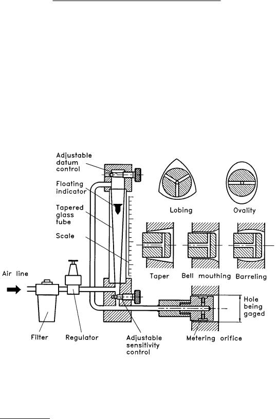
TABLE 6.13 Intrimik® Plus Internal Micrometers by Brown & Sharpe
Range |
B&S Tool No. |
Price ($) |
|
|
|
0.275 in. to 0.350 in. (6–8 mm) |
599-290-35 |
745.40 |
0.350 in. to 0.425 in. (8–10 mm) |
599-290-42 |
745.40 |
0.425 in. to 0.500 in. (10–12 mm) |
599-290-50 |
745.40 |
0.500 in. to 0.600 in. (12–14 mm) |
599-290-60 |
826.70 |
0.600 in. to 0.700 in. (14–17 mm) |
599-290-70 |
826.70 |
0.700 in. to 0.800 in. (17–20 mm) |
599-290-80 |
826.70 |
0.800 in. to 1.0 in. (20–25 mm) |
599-290-100 |
843.60 |
1.0 in. to 1.2 in. (25–30 mm) |
599-290-120 |
843.60 |
1.2 in. to 1.4 in. (30–35 mm) |
599-290-140 |
854.30 |
1.4 in. to 1.6 in. (35–40 mm) |
599-290-160 |
854.30 |
1.6 in. to 2.0 in. (40–50 mm) |
599-290-200 |
933.10 |
2.0 in. to 2.4 in. (50–60 mm) |
599-290-240 |
933.10 |
2.4 in. to 2.8 in. (60–70 mm) |
599-290-280 |
933.10 |
2.8 in. to 3.2 in. (70–80 mm) |
599-290-320 |
950.20 |
3.2 in. to 3.6 in. (80–90 mm) |
599-290-360 |
950.20 |
3.6 in. to 4.0 in. (90–100 mm) |
599-290-400 |
950.20 |
Intrimik Plus Complete Set #5 |
599-290-5 |
3374.60 |
|
|
|
FIGURE 6.57 Air plug gage.
operators to obtain similar results with the same gage. GAGE R AND R blends these two factors together to determine a measuring system’s reliability and its suitability for a particular measuring application. For example, a gage design that meets the GAGE R AND R standards for 50 mm (2 in.) bores may be unsatisfactory on 250 mm (10 in.) bores. A gage that meets a tolerance of 2 m, may not be satisfactory
© 1999 by CRC Press LLC

FIGURE 6.58 TRIOMATIC® electronic bore gage (Courtesy of Brown & Sharpe Manufacturing Company).
TABLE 6.14 TRIOMATIC® Electronic Bore Gages by Brown & Sharpe
Range |
B&S Tool No. |
Price ($) |
|
|
|
0.600 in. to 0.800 in. (12–15 mm) |
62-32005 |
1492.60 |
0.800 in. to 1.000 in. (20–25 mm) |
62-32006 |
1501.20 |
1.000 in. to 1.200 in. (25–30 mm) |
62-32007 |
1515.40 |
1.200 in. to 1.600 in. (30–40 mm) |
62-32008 |
1578.10 |
1.600 in. to 2.000 in. (40–50 mm) |
62-32009 |
1612.40 |
2.000 in. to 2.400 in. (50–60 mm) |
62-32010 |
1639.70 |
2.400 in. to 2.800 in. (60–70 mm) |
62-32011 |
1697.10 |
2.800 in. to 3.200 in. (70–80 mm) |
62-32012 |
1695.90 |
3.200 in. to 3.600 in. (80–90 mm) |
62-32013 |
1702.10 |
3.600 in. to 4.000 in. (90–100 mm) |
62-32014 |
1759.60 |
4.000 in. to 4.400 in. (100–110 mm) |
62-32015 |
1759.60 |
4.400 in. to 4.800 in. (110–120 mm) |
62-32016 |
1759.60 |
TRIOMATIC II Means Sets |
|
|
0.600 in. to 1.200 in. (12–30 mm) |
62-32001 |
2161.00 |
1.200 in. to 2.400 in. (30–60 mm) |
62-32002 |
2663.80 |
2.400 in. to 3.600 in. (60–90 mm) |
62-32003 |
2509.30 |
3.600 in. to 4.800 in. (90–120 mm) |
62-32004 |
2752.70 |
|
|
|
FIGURE 6.59 Form measuring machine.
© 1999 by CRC Press LLC

LLC Press CRC by 1999 ©
TABLE 6.15 Rountest Machines by Mitutoyo/MIT Corp.
Model |
|
RA-112 |
RA334 |
RA-434 |
RA-661 |
|
|
|
|
|
|
Measuring range |
Max. measuring dia. |
11 in. (280 mm) |
11.8 in. (300 mm) |
11.8 in.(300 mm) |
|
|
Max. measuring height |
8.6 in. (220 mm) |
27.6 in. (700 mm) |
13.8 in. (350 mm) |
|
|
Max. loading dia. |
— |
21.7 in. (550 mm) |
20.4 in. (520 mm) |
|
|
Max. loading capacity |
22 lb (10 kg) |
66.1 lb (30 kg) |
132 lb (60 kg) |
|
Detector |
Range |
±0.01 in. (±250 µm) |
±0.012 in. (± 300 µm) |
±0.012 in. (± 300 µm) |
|
|
Measuring force |
|
7–10 gf |
7–10 gf |
|
Turntable |
Rotating accuracy |
(1.6 + 0.3H) µinch |
(1.6 + 0.6H) µinch |
(1.6 + 0.6H) µinch |
|
|
|
(0.04 + 0.3H) µm |
(0.04 + 0.6H) µm |
(0.04 + 0.6H) µm |
|
|
Centering adj. range |
±0.08 in. (±2 mm) |
±0.2 in. (±5 mm) |
±0.2 in. (±5 mm) |
|
|
Leveling adj. range |
|
±1° |
±1° |
|
|
Rotating speed |
|
6 rpm |
2, 4, 6 rpm |
|
Z-axis column |
Straightness |
— |
— |
40 µinch/7.9 in. |
8 µinch/8 in. |
|
|
|
|
1 µm/200 mm |
0.2 µm/200 mm |
|
Parallelism |
— |
— |
120 µinch/7.9 in. |
|
|
|
|
|
80 µinch/13.8 in. |
|
|
|
|
|
3 µm/200 mm |
2 µm/200 mm |
|
Stroke |
10 in. (25 mm) |
|
18.9 in. (480 mm) |
13.8 in. |
Measuring magnifications |
|
100—20,000× |
|
100–50,000× |
100–100,000× |
Dimensions |
Measuring unit |
9.9 × 15.9 × 21.5 in. |
|
24.4 × 19.7 × 36.2 in. |
28.7 × 23.2 × 62.2 in. |
W × D × H |
|
251 × 404 × 576 mm |
|
620 × 500 × 920 mm |
730 × 590 × 1580 mm |
|
Electric unit |
11.4 × 11.8 × 3.6 in. |
|
9.8 × 16.1 × 13 in. |
30.7 × 23.3 × 28.8 in. |
|
|
290 × 300 × 92 mm |
|
250 × 410 × 330 mm |
780 × 592 × 732 mm |
Mass |
Measuring unit |
61.7 lb (28 kg) |
276 lb (125 kg) |
|
298 lb (135 kg) |
|
|
|
|
|
770 lb (350 kg) |
|
Electric (analyzer) unit |
11 lb (5 kg) |
|
24.2 lb (11 kg) |
110 lb (50 kg) |
Base price ($) |
|
17,000 |
45,000 |
60,000 |
60,000 |
|
|
|
|
|
|
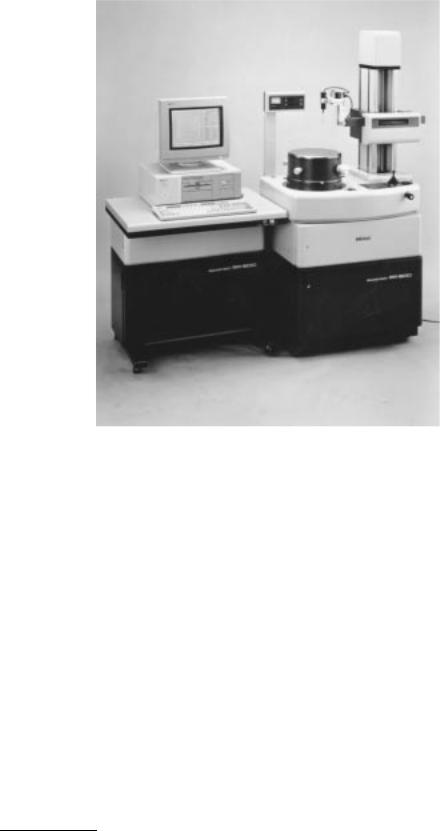
FIGURE 6.60 Fully automatic form measuring machine RA-600 (Courtesy of MITUTOYO/MTI Corporation).
at a tolerance of 1 m. The GAGE R AND R standards will help parts makers identify the best gage for each application and at each tolerance.
The growing acceptance of ISO 9004 as an international quality philosophy is creating significant changes for manufacturers. The most important change that ISO 9004 will create is the need for international GAGE R AND R capability standards and the guarantee of a level playing field. Previously, gage manufacturers and parts makers had many different sets of measuring criteria. Now, in establishing GAGE R AND R capability standards along with ISO 9004 standards, there will be an international set of standards that applies to everyone. A set of measurements from Europe will mean the same as a set from North America or a set from Asia.
The factors that influence GAGE R AND R capability when gaging a bore include:
1.Variation resulting from the bore gage: This variation includes linearity, repeatability, stability, and calibration.
2.Variation resulting from the operation using a bore gage: This variation includes repeatability by an individual operator using the gage and reproducibility by different operators using the same gage.
3.Variation resulting from the production line: Part surface finish, application setup errors, and temperature changes cause this variation.
Dyer company (Dyer, Lancaster, PA 17604) reported the following ranges of these variations for its 830 and 230 series bore gages: linearity ±0.001 mm (±0.000040 in.); repeatability <±0.00025 mm (±0.000010 in.); stability — bore gages are made from a special alloy steel that resists temperature changes
© 1999 by CRC Press LLC
TABLE 6.16 Companies that Make Bore Gages
Company |
Products |
|
|
Brown & Sharpe Manufacturing Company |
All types of bore gages (from calipers to |
Precision Park, 200 Frenchtown Road |
coordinate measuring machines) |
North Kingstown, RI 02852-1700 |
|
Tel: (800) 283-3600 |
|
Fax: (401) 886-2553 |
|
MITUTOYO/MTI Corporation |
The world’s largest manufacturer of precise |
Corporate Headquarters |
measuring instruments; all types of bore |
965 Corporate Blvd. |
gages |
Aurora, IL 60504 |
|
Tel: (708) 820-9666 |
|
Fax: (708) 820-1393 |
|
Deadborn Gage Company |
Air spindles, gaging systems, modular |
32300 Ford Road |
electronic and air-electronic precision |
Garden City, MI 48135 |
gaging instruments |
Tel: (313) 422-8300 |
|
Fax: (313) 422-4445 |
|
The Dyer Company |
Dimensional mechanical and electronic bore |
1500 McGovernville Road |
gages for use in the shop floor |
Box 4966 |
|
Lancaster, PA 17604 |
|
Tel: (800) 631-333 |
|
Fax: (717) 569-6721 |
|
The L.S. Starrett Co. |
Dimensional mechanical and electronic bore |
121 Cresent Street |
gages, coordinate measuring machines, |
Athol, MA 01331-1915 |
optical comparators |
Tel: (508) 294-3551 |
|
Fax: (508) 249-8495 |
|
Flexbar Machine Corporation |
All types of bore gages, including deep-hole |
250 Gibbs Road |
gages and comparators |
Islandia, NY 11722-2697 |
|
Tel: (800) 883-5554 |
|
Fax: (516) 582-8487 |
|
Federal Products Co. |
All types of bore gages: indicator gages, air |
1144 Eddy Street |
gages, electronic gaging products, |
P.O. Box 9400 |
dimensional standards, geometry |
Providence, RI 02940 |
measurement, laboratory gages |
Tel: (800) FED-GAGE, (401) 784-3100 |
|
Fax: (401) 784-3246 |
|
Internet: www.gardnerweb.com/federal/index.html |
|
Comtorgage Corporation |
Dial indicating — expansion plug system |
58 N.S. Industrial Drive |
dedicated to one specific size. Customized |
Slatersville, RI 02876 |
bore gages |
Tel: (401) 765-0900 |
|
Fax: (401) 765-2846 |
|
Marposs Corporation |
In-process and post-process gaging for |
Auburn Hills, MI 48326-2954 |
grinders and lathes, automatic gaging and |
Tel: (800) 811-0403 |
special gaging machines |
Fax: (810) 370-0990 |
|
Rank Taylor Hobson Inc. |
Metrology systems for precision |
2100 Golf Road, Suite 350 |
metalworking and high tolerance |
Rolling Meadows, IL 60008 |
engineering products |
Tel: (800) 464-7265 |
|
Fax: (847) 290-1430 |
|
Sterling Mfg. & Engineering Inc. |
Custom-designed dimensional gages |
7539 19th Mile Road |
including air, manual, electronic and |
Sterling Heights, MI 48314 |
computerized systems |
Tel: (800) 373-0098 |
|
Fax: (810) 254-3601 |
|
© 1999 by CRC Press LLC

TABLE 6.16 (continued) |
Companies that Make Bore Gages |
|
|
|
|
Company |
|
Products |
|
|
|
TRAVERS™ TOOL Co. Inc. |
|
Global Sales Distributer |
128-15 26th Ave. P.O. Box 541 550 |
1 or 2 day delivery at ground rates |
|
Flushing, NY 11354-0108 |
|
|
Tel: (800) 221-0270 |
|
|
Fax: (800) 722-0703 |
|
|
|
|
|
or “hand heat.” The sealed construction ensures performance reliability even under damp or oily conditions; repeatability by an individual operator — the gages are non-tipping and self-centering in both the axial and radial planes of the bore. The operator can keep his/her hands on or off the gage. The operator has no influence when measuring the bore. The automatic alignment of the bore gage results in a highly reproducible reading.
Defining Terms
Dimension: A numerical value expressed in appropriate units of measure and indicated on drawings with lines, symbols, and notes to define the geometrical characteristics of an object.
Tolerance: The total permissible variation of size, form, or location.
Fit: The general term used to signify the range of tightness which may result from the application of a specific combination of allowances and tolerances in the design of mating parts.
ISO System of Limits and Fits: A standardized system of limits and fits, a group of tolerances considered as corresponding to the same level of accuracy for all basic sizes.
Gage: A device for investigating the dimensional fitness of a part for specified function.
Gaging: A process of measuring manufacturing materials to assure the specified uniformity of size and contour required by industries.
References
1.J. W. Greve (ed.), Handbook of Industrial Metrology, ASTM Publications Committee, Englewood Cliffs, NJ: Prentice-Hall, 1967.
2.M. F. Spotts, Dimensioning and Tolerancing for Quantity Production, Englewood Cliffs, NJ: PrenticeHall, 1983.
3.E. R. Friesth, Metrication for Manufacturing, New York: Industrial Press Inc., 1978.
4.J. G. Nee, Fundamentals of Tool Design, 4th ed., Dearborn, MI: Society of Manufacturing Engineers, 1998.
Further Information
F. T. Farago, Handbook of Dimensional Measurement, 3rd ed., New York: Industrial Press Inc., 1994, provides extensive definitions of terms, methods, and measuring setups.
J. Dally, Instrumentation for Engineering Measurements, 2nd ed., New York: Wiley, 1993, provides detailed characteristics of measuring tools and machines.
R. S. Sirohi, Mechanical Measurements, 3rd ed., New York: Wiley, 1991, provides a textbook presentation of the theory of mechanical measurements.
J. D. Meadows, Geometric Dimensioning and Tolerancing: Applications and Techniques for Use in Design, Manufacturing, and Inspection, New York: M. Dekker, 1995, presents basic rules and procedures for good dimensioning practice, providing the background that aids in the solution of dimensioning problems as they arise in day-to-day work.
© 1999 by CRC Press LLC