


where, ΔΛ/Λ and neff /neff are the fractional changes in the periodicity and the effective index, respectively. The relative magnitudes of the two changes depend on the type of perturbation the grating is subjected to; for most applications, the effect due to change in effective index is the dominating mechanism.
Any axial strain, ε, applied to the grating changes the periodicity and the effective index and results in a shift in the Bragg wavelength, given by:
1 |
|
λ |
|
1 |
ΔΛ |
1 |
|
neff |
|
|
|
|
|
= |
|
ε |
+ |
|
|
|
(6.124) |
λ |
ε |
Λ |
n |
ε |
||||||
|
|
|
|
|
|
|
eff |
|
|
|
The first term on the right-hand side is unity, while the second term has its origin in the photoelastic effect. An axial strain on the fiber serves to change the refractive index of both the core and the cladding. This results in the variation in the value of the effective index of glass. The photoelastic or strain-optic coefficient that relates the change in index of refraction due to mechanical displacement is about –0.27. Thus, the variation in neff and Λ due to strain have contrasting effects on the Bragg peak. The fractional change in the Bragg wavelength due to axial strain is 0.73 ε or 73% of the applied strain. At 1550 and 1300 nm, the shifts in the resonance wavelength are 11 nm/%ε and 9 nm/%ε, respectively. With temperature, a FBG at 1500 nm shifts by 1.6 nm for every 100°C rise in temperature [9].
Limitations of Bragg Grating Strain Sensors
The major limitation of Bragg grating sensors is the complex and expensive fabrication technique. Although side-writing is commonly used to manufacture these gratings, the requirement of expensive phase masks increases the cost of the sensing system. In the interferometric technique, stability of the setup is a critical factor in obtaining high-quality gratings. Since index changes of the order of 10–3 are required to fabricate these gratings, laser pulses of high energy levels are necessary. This might reduce laser operating lifetime and lead to increased maintenance expense. Additionally, introducing hydrogen or deuterium into the fiber allows increased index modulation as a result of the irridiation process.
The second major limitation of Bragg gratings is their limited bandwidth. The typical value of the full-width at half maximum (FWHM) is between 0.1 and 1 nm. Although higher bandwidths potentially can be obtained by chirping the index or periodicity along the grating length, this adds to the cost of the grating fabrication. The limited bandwidth requires high-resolution spectrum analyzers to monitor the grating spectrum. Kersey et al. have proposed an unbalanced Mach–Zender interferometer to detect the perturbation-induced wavelength shift [14]. Two unequal arms of the Mach–Zender interferometer are excited by the backreflection from a Bragg grating sensor element. Any change in the input optical wavelength modulates the phase difference between the two arms and results in a time-varying sinusoidal intensity at the output. This interference signal can be related to the shift in the Bragg peak and, hence, the magnitude of the perturbation can be obtained. Recently, modal interferometers have also been proposed to demodulate the output of a Bragg grating sensor [15]. The unbalanced interferometers are also susceptible to external perturbations and hence need to be isolated from the parameter under investigation. Moreover, the nonlinear output might require fringe counting equipment, which can be complex and expensive. Additionally, a change in the perturbation polarity at the maxima or minima of the transfer function curve will not be detected by this demodulation scheme. To overcome this limitation, two unbalanced interferometers can be employed for dynamic measurements.
The cross-sensitivity to temperature fluctuations leads to erroneous strain measurements in applications where the ambient temperature has a temporal variation. Thus, a reference grating that measures the temperature change must be utilized to compensate for the output of the strain sensor. Recently, temperature-independent sensing has been demonstrated using chirped gratings written in tapered optical fibers [16].
Last, the sensitivity of fiber Bragg grating strain sensors might not be adequate for certain applications. This sensitivity of the sensor depends on the minimum detectable wavelength shift at the detection end. Although excellent wavelength resolution can be obtained with unbalanced interferometric detection
© 1999 by CRC Press LLC
techniques, standard spectrum analyzers typically provide a resolution of 0.1 nm. At 1300 nm, this minimum detectable change in wavelength corresponds to a strain resolution of 111 µε. Hence, in applications where strain smaller than 100 µε is anticipated, Bragg grating sensors might not be practical. The dynamic range of strain measurement can be as much as 15,000 µε.
Long-Period Grating Sensor
This section discusses the use of novel long-period gratings as strain sensing devices. The principle of operation of these gratings, their fabrication process, preliminary strain tests, demodulation process, and cross-sensitivity to ambient temperature are analyzed.
Principle of Operation
Long-period gratings that couple the fundamental guided mode to different guided modes have been demonstrated in the past [17, 18]. Gratings with longer periodicities that involve coupling of a guided mode to forward-propagating cladding modes were recently proposed by Vengsarkar et al. [19, 20]. As stated previously, fiber gratings satisfy the Bragg phase-matching condition between the guided and cladding or radiation modes or, another guided mode. This wavelength-dependent phase-matching condition is given by:
β − β = β = |
2π |
(6.125) |
|
Λ |
|||
01 |
|
||
|
|
where Λ is the periodicity of the grating, β01 and β are the propagation constants of the fundamental guided mode and the mode to which coupling occurs, respectively.
For conventional fiber Bragg gratings, the coupling of the forward propagating LP01 mode occurs to the reverse propagating LP01 mode (β = –β01). Since Δβ is large in this case (Figure 6.107(a)), the grating periodicity is small, typically of the order of 1 µm. Unblazed long-period gratings having index variations parallel to the long axis of the fiber couple the fundamental mode to the discrete and circularly-symmetric, forward-propagating cladding modes (β = βn), resulting in smaller values of Δβ (Figure 6.107(b)) and
FIGURE 6.107
© 1999 by CRC Press LLC
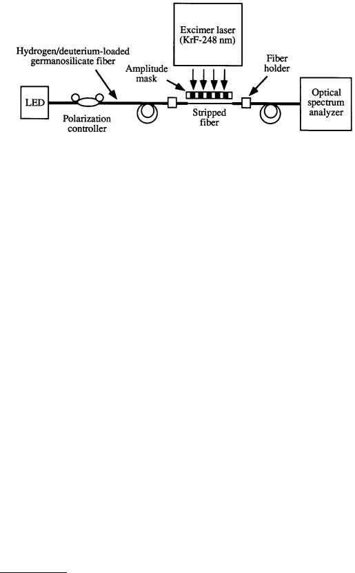
FIGURE 6.108 Setup used to fabricate long-period gratings.
hence periodicities ranging in hundreds of micrometers [19]. The cladding modes attenuate rapidly as they propagate along the length of the fiber due to the lossy cladding-coating interface and bends in the fiber. Since Δβ is discrete and a function of the wavelength, this coupling to the cladding modes is highly selective, leading to a wavelength-dependent loss. As a result, any modulation of the core and cladding guiding properties modifies the spectral response of long-period gratings, and this phenomenon can be utilized for sensing purposes. Moreover, since the cladding modes interact with the fiber jacket or any other material surrounding the cladding, changes in the properties of these ambient materials can also be detected.
Fabrication Procedure
To fabricate long-period gratings, hydrogen-loaded (3.4 mol%) germanosilicate fibers are exposed to 248 nm UV radiation from a KrF excimer laser, through a chrome-plated amplitude mask possessing a periodic rectangular transmittance function. Figure 6.108 shows the setup used to fabricate the gratings. The laser was pulsed at 20 Hz with a 8 ns pulse duration. The typical writing times for an energy of 100 mJ cm–2 pulse–1 and a 2.5 cm exposed length vary between 6 to 15 min for different fibers. The coupling wavelength, λP , shifts to higher values during exposure, due to the photoinduced enhancement of the refractive index of the fiber core and the resulting increase in β01. After writing, the gratings are annealed at 150°C for 10 h to remove the unreacted hydrogen. This high-temperature annealing causes λp to move to shorter wavelengths due to the decay of UV-induced defects and diffusion of molecular hydrogen from the fiber. Figure 6.109 depicts the typical transmittance of a grating. Various attenuation bands correspond to coupling to discrete cladding modes of different orders. A number of gratings can be fabricated at the same time by placing more than one fiber behind the amplitude mask. Moreover, the stability requirements during the writing process are not as severe as those for short-period Bragg gratings.
For coupling to the highest-order cladding-mode, the maximum isolation (loss in transmission intensity) is typically in the 5 to 20 dB range on wavelengths, depending on fiber parameters, duration of UV exposure, and mask periodicity. The desired fundamental coupling wavelength can easily be varied using inexpensive amplitude masks of different periodicities. The insertion loss, polarization-mode dispersion, backreflection, and polarization-dependent loss of a typical grating are 0.2 dB, 0.01 ps, –80 dB, and 0.02 dB, respectively. The negligible polarization sensitivity and backreflection of these devices eliminate the need for expensive polarizers and isolators.
Preliminary experiments were performed to examine the strain sensitivity of long-period gratings written in different fibers [21, 22]. Gratings were fabricated in four different types of fibers: standard dispersion-shifted fiber (DSF), standard 1550 nm fiber, and conventional 980 and 1050 nm single-mode fibers, which for the sake of brevity are referred to as fibers A, B, C, and D, respectively. The strain sensitivity of gratings written in different fibers was determined by axially straining the gratings between
© 1999 by CRC Press LLC
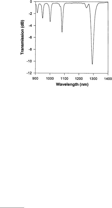
FIGURE 6.109 Typical transmission of a grating.
two longitudinally separated translation stages. The shift in the peak loss wavelength of the grating in fiber D as a function of the applied strain is depicted in Figure 6.110, along with that for a Bragg grating (about 9 nm %ε–1, at 1300 nm) [9]. The strain coefficients of wavelength shift (β) for fibers A, B, C, and D are shown in Table 6.28. Fiber D has a coefficient 15.2 nm %ε–1, which gives it a strain-induced shift that is 50% larger than that for a conventional Bragg grating. The strain resolution of this fiber for a 0.1 nm detectable wavelength shift is 65.75 µε.
The demodulation scheme of a sensor determines the overall simplicity and sensitivity of the sensing system. Short-period Bragg grating sensors were shown to possess signal processing techniques that are complex and expensive to implement. A simple demodulation method to extract information from longperiod gratings is possible. The wide bandwidth of the resonance bands enables the wavelength shift due to the external perturbation to be converted into an intensity variation that can be easily detected.
Figure 6.111 shows the shift induced by strain in a grating written in fiber C. The increase in the loss at 1317 nm is about 1.6 dB. A laser diode centered at 1317 nm was used as the optical source, and the change in transmitted intensity was monitored as a function of applied strain. The transmitted intensity is plotted in Figure 6.112 for three different trials. The repeatability of the experiment demonstrates the feasibility of using this simple scheme to utilize the high sensitivity of long-period gratings. The transmission of a laser diode centered on the slope of the grating spectrum on either side of the resonance wavelength can be used as a measure of the applied perturbation. A simple detector and amplifier combination at the output can be used to determine the transmission through the detector. On the other hand, a broadband source can also be used to interrogate the grating. At the output, an optical bandpass filter can be used to transmit only a fixed bandwidth of the signal to the detector. The bandpass filter should again be centered on either side of the peak loss band of the resonance band. These schemes are easy to implement, and unlike conventional Bragg gratings, the requirement of complex and expensive interferometric demodulation schemes is not necessary [22].
© 1999 by CRC Press LLC