


References
1.J. Blitz, Elements of Acoustics, London: Butterworth, 1964.
2.L. E. Kinsler, A. R. Frey, A. B. Coppens, and T. V. Sanders, Fundamentals of Acoustics, 3rd ed., New York: John Wiley & Sons, 1982.
3.G. Lindstedt, Borrowing the bat’s ear for automation. Ultrasonic measurements in an industrial environment, Dept. of Industrial electrical engineering and automation, Lund Institute of Technology, 1996.
4.G. S. Kino, Acoustic Waves: Devices, Imaging and Analog Signal Processing, Englewood Cliffs, NJ: Prentice-Hall, 1987.
5.S. R. Ruocco, Robot Sensors and Transducers, New York: John Wiley & Sons, 1987.
6.P. H. Sydenham and R. Thorn, Handbook of Measurement Science, Vol. 3, Elements of Change, New York: John Wiley & Sons, 1992.
7.J. Fraden, AIP Handbook of Modern Sensors, Physics, Design and Applications, New York: American Institute of Physics, 1993.
8.H. R. Gallantree, Review of transducer applications of polyvinylidene fluoride, IEEE Proceedings, 130, 219–224, 1983.
9.T. T. Wang and J. M. Herbert, The Applications of Ferroelectric Polymers, London: Chapman & Hall, 1988.
10.C. Z. Rosen, B. V. Hiremath and R. Newnham, Piezoelectricity, New York: American Institute of Physics, 1992.
11.P. Mattila, F. Tsuzuki, H. Väätäjä, and K. Sasaki, Electroacoustic Model for Electrostatic Ultrasonic Transducers with V-Grooved Backplates, in IEEE Trans. Ultrasonics, Ferroelectrics and Frequency Control, Vol. 42, No. 1, January, 1995.
12.P. Holmberg, Instrumentation, Measurements and Applied Signal Processing for Industrial Robot Applications, Ph.D. dissertation No. 334, Dept. of Physics and Measurement Technology, Linköping University, 1994.
13.J. A. Kleppe, Engineering Applications of Acoustics, Boston, 1989.
14.J. S. Bendat and A. G. Piersol, Random Data Analysis and Measurement Procedures, 2nd ed., New York: John Wiley & Sons, 1986.
15.P. Holmberg, Robust ultrasonic range finder — an FFT analysis, Meas. Sci. Technol., 3, 1025–1037, 1992.
6.8Optical Encoder Displacement Sensors
J. R. René Mayer
The detection of angular and linear motion is a key function in a multitude of systems such as machine tools, industrial robots, a variety of instruments, computer mice, etc. Although they are one of many techniques capable of such measurements, the ease with which they are interfaced to digital systems has made them very popular.
Optical encoders are used to measure either angular or linear positions. Those used for angular detection are commonly called rotary or shaft encoders, since they usually detect the rotation of a shaft. Optical encoders encompass a variety of devices, all of which use light as the means to transform movement into electrical signals. All devices have two basic building blocks: a main grating and a detection system. It is the position of one with respect to the other that is detected. The main grating represents the measurement standard. For linear measurements, the main grating, commonly called the scale, is one or more sets of parallel lines of constant or specially coded pitch supported by a substrate. Similarly, a rotary encoder has a grating with radial lines on a disk.
Both linear and rotary encoders can, in principle, be absolute or incremental, although in practice, linear absolute encoders employing optical principles are quite uncommon and have drastically limited
© 1999 by CRC Press LLC
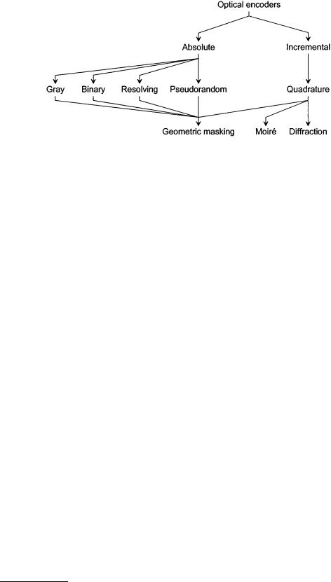
FIGURE 6.66 Classifications of optical encoders based on (1) the nature of the final information provided, (2) the type of signals generated, and (3) the technology used to generate the signals.
performance characteristics (accuracy, resolution, and/or maximum operating speed). Figure 6.66 shows a simplified classification of optical encoders. This classification refers to the nature of the information generated. The incremental encoder detects movement relative to a reference point. As a result, some form of reference signal is usually supplied by the encoder at a fixed position in order to define a reference position. The current position is then incremented (or decremented) as appropriate. Multiple reference marks can also be used, where the distance between successive marks is unique so that as soon as two successive marks have been detected, it becomes possible to establish absolute position from then on. The reference point can also be mechanical. Should power be lost or a signal transmission error occur, then the absolute position is lost and the encoder must return to one or more reference points in order to reset its counters. Unfortunately, a loss of count may not be detected until a reference point is reaccessed. Furthermore, reading errors may accumulate. On the other hand, absolute encoders produce a set of binary signals from which the absolute position can be deduced without the knowledge of the previous motion history. The current position is known right from powering-on. In the case of absolute rotary encoders, single and multiturn devices are available. Multiturn devices use an internal mechanical transmission system to drive a second grating that serves as turn counter.
Most incremental encoders use quadrature signals as output to carry the motion information. Some encoders use one square-wave signal, which is used for position in one direction only. Also, this single square wave can be fed into either a PLC (programmable logic controller) or another electronic interface that converts this signal to a rate or RPM (revolution per minute) for speed indication. However, whenever bidirectional operation is required, quadrature signals are necessary. Quadrature signals come in analog or digital form. The analog form consists simply of a sine and a cosine signal. The number of sinusoidal cycles per unit change of the measured variable (a revolution or 360° for a rotary encoder) determines the basic resolution of the encoder prior to interpolation. The digital form consists of two square-wave trains, 90° (often called electrical degree) out of phase. The 90° phase lag is indispensable in order to detect the motion direction and hence increment or decrement the position counter accordingly. The main optical techniques to generate the quadrature signals are geometric masking, Moiré fringes, and diffraction based. For linear encoders, the basic resolution is related to the distance traveled by the grating in order for the encoder to produce one full quadrature cycle. For rotary encoders, the basic resolution is usually described as the number of quadrature cycles per turn. The resolution of an encoder system can be increased by electronic means. With analog quadrature signals, it is possible to interpolate within each quadrature cycle. The limit of the interpolation factor depends on the quality (mark space, quadrature separation, and jitter) of the basic signals. With square-wave signals, multiplication by a factor of two or four is easily achieved. Increasing the resolution in this manner does not, however, improve the trueness, often called accuracy (or linearity) of the measurement.
© 1999 by CRC Press LLC
FIGURE 6.67 (a) Absolute encoders using a natural binary code of four digits. Four tracks are required. The moving read head has four apertures and is shown in position 7 along the scale. (b) The output of the read head aperture corresponding to the least significant track. It represents the proportion of light area covering the aperture. (c) The binary digit obtained after squaring the raw output signal.
Absolute encoders are classified according to the type of code used. The main four codes are Gray, binary (usually read by vee-scan detection), optical resolving, and pseudorandom. All absolute encoders use geometric masking to generate the code.
Encoder Signals and Processing Circuitry
Absolute Encoders
Direct Binary
Figure 6.67(a) illustrates the concept of an absolute linear optical encoder using a direct binary encoded scale. The fixed scale has n tracks (here n is 4), each providing one bit of a direct binary number. The lowest track (first track from the center of the disk for a rotary encoder) is the most significant digit and has a weight, 2n–1 (here 23), while the upper track is the least significant digit with a weight 20. The track providing the least significant digit has 2n–1 cycles of light and dark records, while the most significant track has 20 or 1 such cycle. For each track, the moving read head has a readout unit consisting of a light source, a mask, and a photodetector. Figure 6.67(b) shows the output from the photodetector, which represents the total intensity of light reaching its surface. As the mask passes over a clear region of the grating, the photodetector output increases, and then decreases. In theory, a truncated triangular wave is obtained, which can easily be converted to a square wave (Figure 6.67(c)) by a suitably chosen thresholding level. The result is a high or 1 for a light record and a low or 0 for a dark one. The position, in base 10, corresponding to the reading head position in Figure 6.67 is
1 × 20 + 1 × 21 + 1 × 22 + 0 × 23 = 7 |
(6.93) |
© 1999 by CRC Press LLC
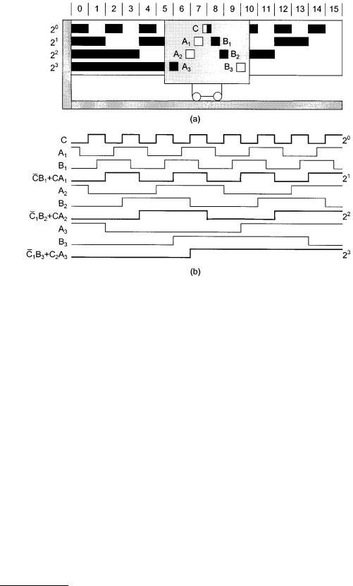
FIGURE 6.68 The vee-scan configuration of reading units in (a) removes the ambiguity associated with a natural binary scale. Simple combinational logic is then used to generate the natural binary readout in (b).
The code configuration just described is not suitable for practical use because some transitions require that two or more bit values change simultaneously. For example, from position 7 to position 8, all bits change values. Unless the change is simultaneous, an incorrect position readout results at some position. This would require that the scale is geometrically perfect, that the read head be perfectly aligned with the scale, and that the electronics are perfectly adjusted and stable over time. This problem is solved either by the use of a vee-scan detection method or the use of a unit-distance code such as the Gray code.
Vee-scan
The vee-scan method uses a V-shape pattern of readout units that removes the potential reading ambiguity of direct binary scales. Stephens et al. [1] indicate the read points at which transitions are detected in Figure 6.68(a). They also describe the conversion of the thresholded output signals to binary code using combinational logic. The primary advantage is that the location tolerance of the transition point of each reading unit need only be ±1/8 of the cycle length for that particular track. For example, ±45° for the most significant track of a rotary encoder disk. Figure 6.68(b) shows a direct binary word obtained through logic combinations of the vee-scan readings.
Gray Code
The use of vee-scan requires additional reading heads as well as processing electronics. The Gray code is a unit-distance code and so only one bit of data changes between representations of two consecutive numbers or successive positions. This removes the possibility of ambiguous readout. It has the following advantages: (1) it is easily converted to direct binary code, and (2) the finest tracks are twice the width of equivalent direct binary code tracks. Figure 6.69(a) shows a Gray code linear scale. Figure 6.69(b) shows a scheme for the conversion from Gray code to binary code and proceeds as follows: (1) the most significant bit (msb) of the binary code equals the msb of the Gray-coded number; (2) add (modulo-2)
© 1999 by CRC Press LLC
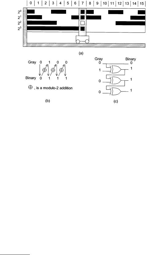
FIGURE 6.69 (a) Gray code allows a transition on only one track between each successive position so that no ambiguity arises. A scheme based on modulo-2 additions converts the Gray code to natural binary code in (b). Exclusive-ORs implement the conversion in (c).
the msb of the binary number to the next significant bit of the Gray-coded number to obtain the next binary bit; and (3) repeat step (2) until all bits of the Gray-coded number have been added modulo-2. The resultant number is the binary equivalent of the Gray-coded number. The modulo-2 addition is equivalent to the action of an exclusive-OR. Figure 6.69(c) shows a simple circuit using combinational logic to perform Gray to binary conversion. Sente et al. [2] suggest the use of an external ROM to convert the code where the input coded word is the address and the data is the output coded word. Using a 16-bit ROM for a 12-bit code, Sente et al. [2] suggest using the remaining 4 bits to implement a direction signal. Stephens et al. [1] describe the use of vee-scan with a gray code scale for even better robustness.
Pseudorandom Code
Pseudorandom encoding allows the use of only two tracks to produce an absolute encoder. One track contains the pattern used to identify the current position, while the other is used to synchronize the reading of the encoded track and remove ambiguity problems. A pseudorandom binary sequence (PRBS) is a series of binary records or numbers, generated in such a way that any consecutive series of n digits is unique. Such code is called chain code, and it has the property that the first n – 1 digits of an n-bit word are identical to the last n – 1 digits of the previous code word. This allows their partial overlapping on a single track. A PRBS of length 2n – 1 is defined by:
XN(j) |
|
j = 0, 1, ¼, 2n−1 |
(6.94) |
|
The code can be generated by reading the nth stage of a feedback shift register after j shifts. The register must be initialized so that at least one of the registers is nonzero and the feedback connection implements the formula
X(0) = X(n)Åc(n -1) X(n -1) Å ¼ Å c(1) X(1) |
(6.95) |
© 1999 by CRC Press LLC

TABLE 6.18 Shift-Register Feedback Connections for Generating Pseudorandom Binary Sequences
n |
Length |
Direct sequence |
Reverse sequence |
|
|
|
|
4 |
15 |
1, 4 |
3, 4 |
5 |
31 |
2, 5 |
3, 5 |
6 |
63 |
1, 6 |
5, 6 |
7 |
127 |
3, 7 |
4, 7 |
8 |
255 |
2, 3, 4, 8 |
4, 5, 6, 8 |
9 |
511 |
4, 9 |
5, 9 |
10 |
1023 |
3, 10 |
7, 10 |
11 |
2047 |
2, 11 |
9, 11 |
12 |
4095 |
1, 4, 6, 12 |
6, 8, 11, 12 |
13 |
8191 |
1, 3, 4, 13 |
9, 10, 12, 13 |
14 |
16,383 |
1, 6, 10, 14 |
4, 8, 13, 14 |
|
|
|
|
where the c coefficients are 0 or 1. The feedback registers for which c is 1 are listed in Table 6.18 for values of n from 4 to 14. The following is a PRBS for n = 4 with the pseudocode obtained using all registers set to 1 initially, 111101011001000. For a rotary encoder disk, the 15 sectors would have a 24° width.
Petriu [3, 4] describes a possible configuration of a PRBS disk that uses a PRBS track and a synchronization track (Figure 6.70), together with the processing method to reconstitute the position in natural binary. Table 6.18 gives the reverse feedback configuration. The shift register is initially loaded with the current n-tuple. Then the reverse logic is applied recurrently until the initial sequence of the PRBS is reached. At this point, the n-bit counter represents the value of j. For a rotary encoder (j 360)/(2n – 1) is the current angular position; whereas for a linear encoder, the position is j P where P is the scale record length or pitch. Petriu [4] suggests that in order to allow nonambiguous bidirectional reading, n + 1 heads are used on the PRBS track. The synchronization track has a series of 0s and 1s in records of the same width as the PRBS track and in phase. There is a P/2 shift, where P is the record’s length between the A head on the synchronization track and the n + 1 read heads on the PRBS track. The n + 1 records are updated on a trigger from the A signal. This ensures that the n + 1 heads are closely aligned with the PRBS record mid-position. A second read head called B on the synchronization track is shifted by P/2 relative to A. A and B are in quadrature, which allows their simultaneous use to generate a motion direction signal. The correct n-tuple, i.e., the lower or upper subset, is selected on the basis of the moving direction and is then converted to natural binary by reverse feedback. Petriu [4] also suggests a simple means of increasing the resolution by a factor of 2 using some additional electronics. He also proposes a scheme to use an arbitrary (not 2n – 1) number of sectors, but this requires a third track and some additional correction electronics to handle the last n – 1 records of a disk, since these are no longer PRBS patterns. Tomlinson [5] proposes another method for truncation of the PRBS sequence that does not require a third track. Instead, particular codes were removed by applying additional logic in the direct and reverse feedback logic.
Ross and Taylor [6] and Arsic and Denic [7] suggest ways of reducing the number of reading heads by accumulating readings into a shift register so that a minimum of two heads are sufficient to read the PRBS track. However, on start-up, the correct position is not known until the encoder has moved so that all registers have been updated. This type of encoder is therefore not completely absolute because it does not indicate its correct position on start-up. Finally, Arazi [8] mentions the use of a ROM that stores the translation table, as an alternative to a logic circuit.
Optical Resolving
This method has similarities with its electromagnetic counterpart and depends on the generation of a sine and a cosine signal pair per encoder shaft revolution. The resolution and accuracy of this encoder depend on its ability to generate signals that conform to their ideal waveforms and the resolving power of the electronic circuit responsible for performing the rectangular to polar conversion to produce angular
© 1999 by CRC Press LLC

FIGURE 6.70 Pseudorandom shaft encoder with a simple synchronization track to validate the readout from the n-tuple read by the reading heads H(i), i = n, …, 1. The circuit is a simplified code conversion to binary based on the reverse feedback logic. The counter counts the number of steps required to return to the initial sequence.
© 1999 by CRC Press LLC