

Micro-Cap v7.1.6 / RM
.PDFExample
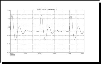
.MODEL S1 VSWITCH (RON=1 ROFF=1K VON=1 VOFF=1.5)
Model parameters |
|
|
||
Name |
Parameter |
Units |
Default |
|
RON |
On resistance |
Ohms |
1 |
|
ROFF |
Off resistance |
Ohms |
1E6 |
|
VON |
Control voltage for On state |
V |
1 |
|
VOFF |
Control voltage for Off state |
V |
0 |
|
Model Equations |
|
|
||
VC = |
Voltage across the control nodes |
|
|
|
LM = |
Log-mean of resistor values = ln((RON•ROFF)1/2) |
|||
LR = |
Log-ratio of resistor values = ln(RON/ROFF) |
|
||
VM= |
Mean of control voltages = (VON+VOFF)/2 |
|
||
VD = |
Difference of control voltages = VON-VOFF |
|
||
k |
= |
Boltzmann's constant |
|
|
T |
= |
Analysis temperature |
|
|
RS = |
Switch output resistance |
|
|
|
If VON > VOFF If VC >= VON
RS = RON If VC <= VOFF RS = ROFF
If VOFF < VC < VON
RS = exp(LM + 3•LR•(VC-VM)/(2•VD) - 2•LR•(VC-VM)3/VD3)
If VON < VOFF If VC <= VON
RS = RON If VC >= VOFF RS = ROFF
If VOFF > VC > VON
RS = exp(LM - 3•LR•(VC-VM)/(2•VD) + 2•LR•(VC-VM)3/VD3)
Noise effects
Noise is modeled as a resistor equal to the resistance found during the DC operating point. The thermal noise current is calculated as follows:
I= sqrt(4•k•T/RS)
467

Sample and hold source
SPICE format
There is no equivalent Sample and Hold device in SPICE or PSpice.
Schematic format
PART attribute <name>
Examples
S1
S10
SA
INPUT EXPR attribute <input expression>
Examples
V(1,2)
V(10,20)*I(R1)
V(INPUT)
SAMPLE EXPR attribute <sample expression>
Examples
V(1,2)>1.2
V(5)>1.1 AND V(4) >1.2
I(RL)>1e-3
PERIOD attribute <sampling_period>
Examples 100ns tmax/100 1U
This device is an ideal sample and hold. It samples <input expression> when <sampling_period> is true or every sample period seconds. The behavioral modes are distinguished as follows:
468 Chapter 22: Analog Devices

Sine source
Schematic format
PART attribute <name>
Examples
S1
MODEL attribute <model name>
Example
Line60
The Sine source is similar to the SPICE SIN independent voltage source. Unlike the SPICE source, it uses a model statement.
Model statement form
.MODEL <model name> SIN ([model parameters])
Example
.MODEL V1 SIN (F=1Meg A=0.6 DC=1.5)
Model parameters |
|
|
|
Name |
Parameter |
Units |
Default |
F |
Frequency |
Hz |
1E6 |
A |
Amplitude |
V |
1.0 |
DC |
DC level |
V |
0.0 |
PH |
Phase shift |
Radians |
0.0 |
RS |
Source resistance |
Ω |
0.001 |
RP |
Repetition period of exponential S |
0.00 |
|
TAU |
Exponential time constant |
S |
0.00 |
Model Equations
If TAU = 0 then
V = A•sin (2•π •F•TIME + PH) + DC
Else
V = A•e(-T/TAU)•sin (2•π •F•TIME + PH) + DC
where T = TIME mod RP.
470 Chapter 22: Analog Devices

Subcircuit call
SPICE format
X<name> [node]* <subcircuit name>
+[PARAMS: <<parameter name>=<parameter value>>*]
+[TEXT: <<text name>=<text value>>*]
Examples
X1 10 20 AMP
XDIFF 100 200 DIFF PARAMS: GAIN=10
Schematic format
PART attribute <name>
Example
X1
NAME attribute <subcircuit name>
Example
FILTER
FILE attribute [<file name>]
Example
MYFILE.MOD
PARAMS: attribute
[<<parameter name>=<parameter value>>*]
Example
CENTER=10KHZ BW=1KHZ
TEXT: attribute
[<<text name>=<text value>>*]
Example
JEDEC="FILENAME"
472 Chapter 22: Analog Devices
.SUBCKT CLIP 1 2
+ PARAMS: LOW=0 HIGH=10
Any of these calls are legal:
X1 |
1020CLIP |
;RESULTSINLOW=0,HIGH=10 |
X2 |
1020CLIPPARAMS:LOW=1HIGH=2 ;RESULTSINLOW=1,HIGH=2 |
|
X31020CLIPPARAMS:HIGH=4 |
;RESULTSINLOW=0,HIGH=4 |
|
The SPICE keyword or schematic TEXT: attribute lets you pass text parameters to the subcircuit. <text name> is the name of the text parameter and <text value> defines the value it will assume if the parameter is not included in the subcircuit call. For example:
.SUBCKTSTIMULUS1234 +TEXT:FILE="T1.STM"
Either of these calls are legal:
X110203040STIMULUS |
;RESULTSINFILE="T1.STM" |
X210203040STIMULUSTEXT:FILE="P.STM" |
;RESULTSINFILE="P.STM" |
Using the subckt component in an MC7 schematic circuit file is easy. First, you must enter the subcircuit into the Component library using the Component editor. This requires entering:
•Subckt Name: Use any unique name. To avoid confusion, it should be the same as the name used in the SUBCKT control statement, although this is not strictly necessary.
•Shape Name: Use any suitable shape.
•Definition: Use SUBCKT.
Once these items have been entered, the pin assignments must be defined. These define where the node numbers called out in the SUBCKT control statement go on the shape. Pins are assigned by clicking in the Shape drawing area and naming the pin with the subckt node number. The pin is then dragged to the desired position on the shape.
The subckt is then placed in the schematic in the usual way.
To see how subckts are called, see the sample circuit files SUBCKT1 and PLA2.
474 Chapter 22: Analog Devices

Switch
Schematic format
PART attribute <name>
Examples
S1
VALUE attribute
<[V | T | I]>,<n1,n2> [,<ron>[,<roff>]]
Examples
V,1,2
I,2ma,3ma
T,1ms,2ms,50,5Meg
This is the oldest of three types of switches. The newer S and W switches exhibit a slower, but smoother transition between the off and on states.
There are three types of dependent switches; current-controlled, voltage-con- trolled, and time-controlled.
The switch is a four-terminal device. A current sensing inductor must be connected across the two input nodes when the current-controlled switch option is used. Voltage-controlled switches are controlled by the voltage across the two input nodes. Time dependent switches use the transient analysis time variable to control the opening and closing of the switch.
The two controlling nodes for a time-controlled switch are not used and may be shorted to ground or to the two output nodes to reduce the node count by two.
In transient analysis, care must be taken in choosing the time step of the simulation. If the time step is too large, the switch might never turn on. There must be at least one time point within the specified window for the switch to close or open.
The switch parameter syntax provides for a normally-on or a normally-off switch. A normally-on switch is one that is on outside the specified window and off inside the window. A normally-off switch is one that is off outside the window and on inside the window.
475