Example 1
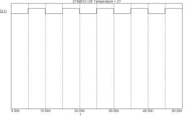
The first example is a single output device exhibiting a single zero pulse starting at 10ns and lasting to 20ns. There are no loops.
U1 STIM(1,1) $G_DPWR $G_DGND + 1 ;Output node number
+IO_STD
+0NS 1
+10NS 0
+20NS 1
Figure 23-4 Stimulus waveform for examples 1 and 2
Example 2
The next example produces the same output as the first example, but uses relative times instead of absolute times.
U1 STIM(1,1) $G_DPWR $G_DGND + 1 ;Output node number
+IO_STD
++ 0NS 1
++ 10NS 0
++ 10NS 1
The first transition occurs at 0ns, the next at 0ns+10ns=10ns, and the last occurs at 0ns+10ns+10ns = 20ns, the same as in the first example.
Example 3
This shows how to create a single output alternating 0 - 1 sequence.
U1 STIM(1,1) $G_DPWR $G_DGND + 1 ;Output node number
+IO_STD
+0NS 0
+LABEL=begin
++ 5NS 1
++ 5NS 0
++ 5NS GOTO begin -1 TIMES
Figure 23-5 Stimulus waveform for example 3
Execution begins at T=0ns with the output set to '0'. At T=5ns (0ns+5ns), the output is set to '1'. At T=10ns (5ns+5ns), the output is set to '0'. At T=15ns (10ns+5ns), the GOTO is executed and control passes to the '+5ns 1' statement following the 'LABEL=begin' statement. The time instruction (+5ns) is ignored and the output is set to '1'. The <time> value of the first statement executed as a result of a GOTO is always ignored. The same waveform can be achieved by replacing the portion "+ LABEL=begin...+ 5NS GOTO begin -1 TIMES" with:
+REPEAT FOREVER
++ 5NS 1
++ 5NS 0
++ 5NS ENDREPEAT
578 Chapter 23: Digital Devices
Example 4
This example shows how to create a two-output alternating 0 - 1 sequence.
U1 STIM(2,11) $G_DPWR $G_DGND + 1 2 ;Output node numbers
+IO_STD
+LABEL=begin
++ 0NS 00
++ 5NS 01
++ 5NS 10
++ 5NS 11
++ 5NS GOTO begin -1 TIMES
Figure 23-6 Stimulus waveform for example 4
Notice that the STIM(2,11) statement specifies two outputs with a binary format. Execution begins at the '+ 0NS 00' statement, where the outputs are set to '00'. The next command, '+ 5NS 01', occurs at T=5ns (0ns+5ns), where the outputs are set to '01'. The next command, '+ 5NS 10', occurs at T=10ns (5ns+5ns), where the outputs are set to '10'. The next command, '+ 5NS 11', occurs at T=15ns (10ns+5ns), where the outputs are set to '11'. The next command, '+ 5NS GOTO begin -1 TIMES', occurs at T=20ns (15ns+5ns). It causes a jump to the statement '+ 0NS 00' (the one following the 'LABEL=begin command'. From here the loop simply repeats until the end of the simulation run.
Example 5
This next example shows how to use the INCR and UNTIL commands.
U1 STIM(8,44) $G_DPWR $G_DGND
+ 1 2 3 4 5 6 7 8 |
|
+ IO_STD |
|
+ LABEL=begin |
|
+ + 0NS INCR BY 01 |
;Increment by hex 01 |
+ + 10NS GOTO begin UNTIL GE 06 |
;Count until 06 hex |
+ + 10NS F0 |
;After 10NS goto F0 hex |
+ + 10NS F1 |
;After 10NS goto F1 hex |
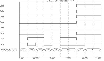
Figure 23-7 Stimulus waveform for example 5
This STIM generates eight outputs. The sequence begins with the eight outputs set to 00 hex during the operating point. At 0ns, the outputs are incremented by 01 from 00 to 01. At 10ns, the GOTO-UNTIL is checked and found to be true.
Control is passed to the INCR statement following the LABEL=begin, where the outputs are incremented to 02. At T = 50ns, the outputs have reached 05 and the GOTO-UNTIL test sends execution back to the INCR command. This command at T=50ns, increments the outputs to 06. At T = 60ns, the outputs are at 06 and the GOTO-UNTIL test fails. Execution drops to the '+10NS F0' command and T=70ns. The outputs go to F0 and then execution drops to the '+10NS F1' command and T=80ns. The outputs go to F1 and the STIM program terminates, leaving the outputs at F1 for the remainder of the run.
580 Chapter 23: Digital Devices

The File Stimulus device
The File Stimulus device lets you import digital waveforms from a text file. This device lets you import digital waveforms from other simulators or from the MC7 output file (with some editing).
File Stimulus input file format
The File Stimulus device expects to read a file in the following format:
<Header>
One or more blank lines <Transition tables>
<Header>
This consists of the following: [TIMESCALE=<time scale value>] [<first signal name>...<last signal name>]
OCT(<signal name bit 3>...<signal name of lsb>)...
HEX(<signal name bit 4>...<signal name of lsb>)...
<Header> contains the optional [TIMESCALE=<value>] line and a single line list of signal names. The signal names may be separated by spaces, commas, or tabs. The line may not be continued with the continuation character '+'. The line may contain up to 256 signals. The signal names will be associated with signal values from the <Transition tables>, in the same order.
The optional OCT(<sig1>, <sig2>, <sig3>) radix function lets you declare segments of the transition table as octal numbers. It decodes each octal digit from the table into three binary values and assigns these values to the three signal names. The function must have exactly three signal names as arguments and it consumes one octal digit from each row in the transition table.
The optional HEX(<sig1>, <sig2>, <sig3>, <sig4>) radix function lets you declare segments of the transition table as hex numbers. It decodes each hex digit into four binary values and assigns the values to the four signal names. The function must have exactly four signal names as arguments and it consumes one hex digit from each row in the transition table.
Signal names not using the HEX or OCT function are assumed to be in binary format. Each signal name in binary format consumes exactly one binary digit from the transition table.
The total number of physical outputs is:
Outputs = binary names + 3•octal names + 4•hex names
The total number of digits in the state portion of the transition table will be:
Digits = binary names + OCT statements + HEX statements
<Transition tables>
The transition table format is as follows:
<time> <state value>*
<Transition tables> start on the first non-blank line following the Header. Each line must contain a transition time, <time>, followed by a space or tab, followed by one or more <state values>.
<time>
<time> is always expressed as an integer. It may be absolute or, if preceded by a '+', relative to the previous time. The <time> value is multiplied by the <time scale value> to get the actual transition time.
<value>
Each digit of <value> provides one state for each binary signal name, three states for each OCT set of three signal names, or four states for each HEX group of four signal names. Each digit is stripped from the table and assigned to the signal names in the same left-to-right order. The list of valid digits are:
|
Binary |
Octal |
Hex |
|
|
|
|
Logic state |
0,1 |
0-7 |
0-F |
|
|
|
|
Unknown |
X |
X |
X |
|
|
|
|
High impedance |
Z |
Z |
Z |
|
|
|
|
Rising |
R |
R |
None |
|
|
|
|
Falling |
F |
F |
None |
|
|
|
|
Table 23-21 File Stimulus device digit codes
582 Chapter 23: Digital Devices
Transition Table example
TIMESTEP=1NS
A B C D HEX(A4,A3,A2,A1) OCT(D3,D2,D1)
00000F3 ; transition time =0
1000104 ; transition time =1NS
+2 |
001015 |
; transition time =3NS (1NS+2NS) |
5 |
001126 |
; transition time =5NS |
SPICE format
U<name> FSTIM(<no. of outputs>) +<digital power node> <digital ground node> +<node>*
+<I/O model name>
+ FILE=<stimulus file name> +[IO_LEVEL=<interface subckt select value>] +[SIGNAMES=<signal names from stimulus file>]
Schematic format
PART attribute <name>
Example
FS1
I/O MODEL attribute <I/O model name>
Example
IO_STD
FILE attribute <file name>
Example
MYFILE.STM
SIGNAMES attribute
<signal names from stimulus file>
Example
CLEAR PRESET Q QB
IO_LEVEL attribute <interface subckt select value>
Example 0
POWER NODE attribute <digital power node>
Example
$G_DPWR
GROUND NODE attribute <digital ground node>
Example
$G_DGND
Definitions
<no. of outputs>
In a SPICE file, this specifies the number of signals or output nodes. For schematic components, this value is defined when the component is first entered into the Component library. Simply picking an FSTIM device from the Component library menu supplies this information.
<digital power node> <digital ground node> These nodes are used by the I/O circuits.
<node>*
For SPICE circuit components, this list defines the output nodes. For a schematic circuit component, this data is automatically acquired from the output node numbers or node names. Node names are defined by the user by placing grid text on the output nodes. The number of names in this list must equal <no. of outputs>.
<I/O model name>
This name references an I/O model statement which specifies the electrical interface to be used when an analog node and digital node connect. It also specifies the DRVH and DRVL impedances that determine signal strengths when an output is wired to another digital output.
584 Chapter 23: Digital Devices
FILE=<stimulus file name>
This is the stimulus file name specified as a text string enclosed in double quotes.
Example "MyFile.stm"
[IO_LEVEL=<interface subcircuit select value>]
This selects one of four interface circuits named in the I/O model. These circuits are used at the digital/analog interface.
Example 1
[SIGNAMES=<signal names from stimulus file>]
This selects one or more of the signal names from the stimulus file <Header> for use by one of the output nodes,<node>*. The signal from the stimulus file is assigned to drive the <node> positionally associated with it. If no signal names are specified, then the program will expect to find signal names in the stimulus file that match the output node names ,<node>*. This command must be the last command in a SPICE file component specification.
Example1
U1 FSTIM(3) $G_DPWR $G_DGND + A B C
+IO_FS +FILE="PATTERN.STM"
In Example 1, there is no SIGNAMES command, so the stimulus file PATTERN.STM must contain the signal names A, B, and C in the <Header>. The signals for A, B, and C would be assigned to the FSTIM outputs A, B, and C.
Example 2
U2 FSTIM(3) $G_DPWR $G_DGND
+A B C +IO_FS
+FILE="PATTERN.STM"
+SIGNAMES=X Y Z
585
In Example 2, there is a SIGNAMES command, so the stimulus file PATTERN.STM must contain the signal names X, Y, and Z in the <Header>. The signals for X, Y, and Z would be assigned to the FSTIM outputs A, B, and C.
Example 3
U3 FSTIM(4) $G_DPWR $G_DGND
+TOM RAY CAR TALK +IO_FS +FILE="PATTERN.STM"
+SIGNAMES=CLIK CLAK
The stimulus file PATTERN.STM must contain the signal names CLIK, CLAK, CAR, and TALK. The signals for CLIK and CLAK would be assigned to the FSTIM outputs TOM and RAY respectively. The signals for CAR and TALK would be assigned to the FSTIM outputs CAR and TALK respectively.
The sample circuit FSTIM8 illustrates the use of the file stimulus device.
586 Chapter 23: Digital Devices