

Micro-Cap v7.1.6 / RM
.PDFPUT
This circuit is a macro model for a PUT, a Programmable Unijunction Transistor. The macro equivalent circuit is as follows:
Figure 21-16 PUT macro equivalent circuit
The parameter definitions are as follows:
Parameter |
Definition |
IH |
DC holding current |
IGT |
Gate trigger current |
TON |
Turn-on time |
VTMIN |
Minimum anode to cathode on-state voltage |
VDRM |
Maximum repetitive peak off-state voltage |
DVDT |
Critical rate of rise of off-state voltage |
TQ |
Turn-off time |
K1 |
Tweak factor for DVDT |
K2 |
Tweak factor for TQ |
See the circuit THY1 for an example of the use of this macro.
347
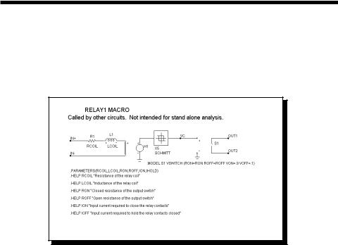
RELAY1
This relay model includes a user-specified coil resistance and inductance. The coil current is sensed and converted to a voltage by H1 which drives a Schmitt macro to provide hysteresis between the ION and IHOLD currents. The output of the Schmitt drives a standard voltage controlled switch S1.
Figure 21-17 RELAY1 macro equivalent circuit
The parameter definitions are as follows:
Parameter |
Definition |
RCOIL |
Resistance of the relay coil |
LCOIL |
Inductance of the relay coil |
RON |
Closed resistance of the output switch |
ROFF |
Open resistance of the output switch |
ION |
Input current required to close the relay contacts |
IOFF |
Input current required to hold the relay contacts closed |
See the circuit RELAY for an example of the use of this macro.
348 Chapter 21: Analog Behavioral Building Blocks
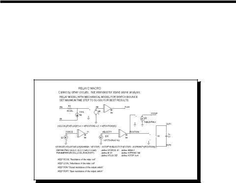
RELAY2
This relay model includes a flux circuit and derives a magnetizing force from the flux. It then algebraically sums the magnetizing, stop, friction and restoring spring forces acting on the relay plunger to arrive at a net force which is integrated once to get the plunger velocity and again to get the plunger position. This plunger position directly controls the switch contacts.
Figure 21-18 RELAY2 macro equivalent circuit
The parameter definitions are as follows:
Parameter |
Definition |
RCOIL |
Resistance of the relay coil |
LCOIL |
Inductance of the relay coil |
RON |
Closed resistance of the output switch |
ROFF |
Open resistance of the output switch |
See the circuit RELAY for an example of the use of this macro.
349
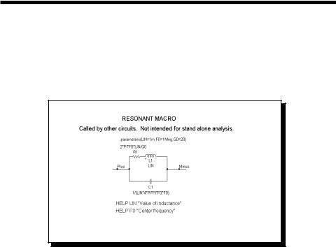
RESONANT
This macro implements a resonant circuit with a resistor, capacitor, and inductor. The L value is entered as an input parameter, LIN. The C value is computed from the LIN and F0 input parameters. The resistor is computed from all three input parameters. The implementation is as follows:
Figure 21-19 RESONANT macro equivalent circuit
The parameter definitions are as follows:
Parameter |
Definition |
LIN |
Value of inductance |
F0 |
Center frequency |
Q0 |
Quality factor |
350 Chapter 21: Analog Behavioral Building Blocks
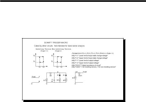
SCHMITT
This circuit is a macro model for a Schmitt trigger, a circuit with a large number of uses, including noise filtering, hysteresis, and level shifting. The circuit looks likethis:
Figure 21-20 SCHMITT macro equivalent circuit
The parameter definitions are as follows:
Parameter |
Definition |
X1 |
Lower limit of input state change voltage |
X2 |
Upper limit of input state change voltage |
Y1 |
Lower limit of output voltage |
Y2 |
Upper limit of output voltage |
ROUT |
Output Resistance of circuit |
SIGN |
-1 for inverting version, 1 for non-inverting version |
See the circuit OSC1 for an example of the use of this macro.
351
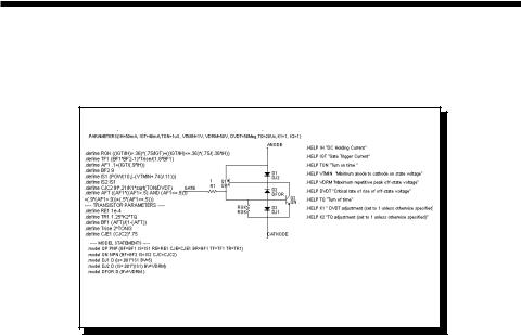
SCR
This circuit is a macro model for a silicon controlled rectifier or SCR. The macro equivalent circuit is as follows:
Figure 21-21 SCR macro equivalent circuit
The parameter definitions are as follows:
Parameter |
Definition |
IH |
DC holding current |
IGT |
Gate trigger current |
TON |
Turn-on time |
VTMIN |
Minimum anode to cathode on-state voltage |
VDRM |
Maximum repetitive peak off-state voltage |
DVDT |
Critical rate of rise of off-state voltage |
TQ |
Turn-off time |
K1 |
Tweak factor for DVDT |
K2 |
Tweak factor for TQ |
See the circuit THY1 for an example of the use of this macro.
352 Chapter 21: Analog Behavioral Building Blocks
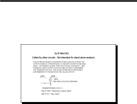
SLIP
The SLIP macro models hysteresis, or backlash. The output is zero within the slip zone, -DX to +DX. Outside of the hysteresis zone, the output is proportional to the input. The output is clipped to MAX.
This function is implemented with the SLIP macro:
Figure 21-22 SLIP macro equivalent circuit
A pair of input parameters, DX and MAX, define the slip zone and the maximum output level. The function is constructed with an NTVOFV Function table source.
Parameter |
Definition |
DX |
Slipvalue |
MAX |
Maximum value |
See the circuit SYSTEM2 for an example of the use of this macro.
353

SPARKGAP
This is a macro circuit model for a spark gap arrestor.
Figure 21-23 SPARKGAP macro equivalent circuit
Parameter |
Definition |
VTHRES |
Voltage at which the spark-gap strikes |
VARC |
Voltage across the spark-gap once struck |
ISUS |
Sustaining current under which the arc is stopped |
RNEG |
Negative resistance once struck |
LPL |
Lead inductance |
RPL |
Flux loss associated with LPL |
CPAR |
Gap capacitance |
CARC |
Arc capacitance |
See the circuit SPARK for an example of the use of this macro.
354 Chapter 21: Analog Behavioral Building Blocks

SUB
A common requirement is to subtract two analog signals. The desired function is:
VOut(t) = ka Va(t) - kb Vb(t)
This function is implemented with the SUB macro:
Figure 21-24 SUB macro equivalent circuit
The two input parameters, KA and KB, scale each input. The scaled input signals are then subtracted to produce the output. This implementation is done with an NFV function source.
Parameter |
Definition |
KA |
Multiplier of input A |
KB |
Multiplier of input B |
See the circuit SYSTEM2 for an example of the use of this macro.
355
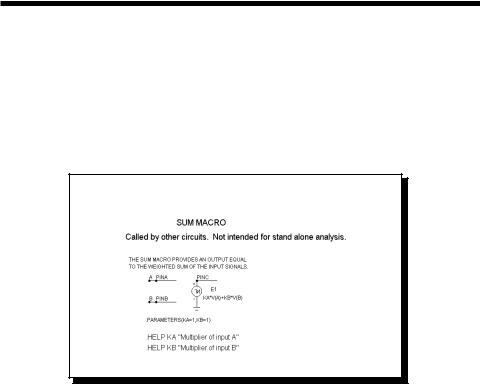
SUM
Many systems simulations call for a function to perform the analog addition of two signals. The desired function is:
VOut(t) = ka Va(t) + kb Vb(t)
This function is implemented with the SUM macro:
Figure 21-25 SUM macro equivalent circuit
The two input parameters, KA and KB, scale each input. The scaled input signals are then added to produce the output.
Parameter |
Definition |
KA |
Multiplier of input A |
KB |
Multiplier of input B |
See the circuit SYSTEM2 for an example of the use of this macro.
356 Chapter 21: Analog Behavioral Building Blocks