

Micro-Cap v7.1.6 / RM
.PDFDIF
The differentiator is the inverse of the integrator. It provides an output which is a scaled version of the time derivative of the input signal:
VOut(t) = scale d(VIn(t))/dt
This function is implemented with the DIF macro:
Figure 21-6 DIF macro equivalent circuit
The single input parameter, SCALE, multiplies or scales the derivative. This particular implementation has a buffered output, allowing it to drive very low impedance networks.
337
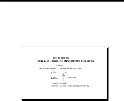
DIV
Occasionally, system blocks require a function that divides two analog signals. The desired function is:
VOut(t) = scale Va(t)/Vb(t)
This function is implemented with the DIV macro:
Figure 21-7 DIV macro equivalent circuit
The single input parameter passed to the macro by the calling circuit, SCALE, multiplies or scales the ratio of the two input waveforms at the output.
338 Chapter 21: Analog Behavioral Building Blocks
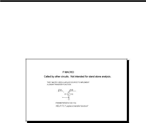
F
This system block merely provides a convenient shape to house a general linear transfer function, F(S). It is implemented with a Laplace LFVOFV source.
F(s) = VOut(s) /VIn(s)
This function is implemented with the F macro:
Figure 21-8 F macro equivalent circuit
The input parameter is an expression representing the complex frequency transfer function.
See the circuit SYSTEM2 for an example of the use of this macro.
339

FSK
This block provides a frequency-shift keyer encoder.
Figure 21-9 FSK macro equivalent circuit
The input parameters are as follows:
Parameter |
Definition |
WMAG |
Magnitude of the output waveform |
NC0 |
Number of cycles of the output waveform that will occur |
|
in the duration of a single zero bit of the input waveform |
NC1 |
Number of cycles of the output waveform that will occur |
|
in the duration of a single one bit of the input waveform |
TB |
Duration of a single bit in seconds |
See the circuit FSK2 for an example of the use of this macro.
340 Chapter 21: Analog Behavioral Building Blocks
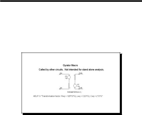
GYRATOR
The gyrator can be used to scale a resistive impedance. It can also transform an inductive impedance to a capacitive impedance or a capacitive impedance to an inductive impedance.
This function is implemented with two cross-referenced linear dependent VOFI sources.
Figure 21-10 GYRATOR macro equivalent circuit
A single parameter, G, determines the impedance transformation as follows:
Req = 1/(R*G*G)
Leq = C/(G*G)
Ceq = L*G*G
See the circuit GYRTEST for an example of the use of this macro.
341
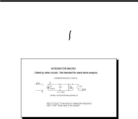
INT
One of the most useful functions for system modeling is the integrator. Ideally this function provides an output which is the integral of the input signal:
 t
t
VOut(t) = vinit + scale VIn(t) dt
 0
0
This function is implemented with the INT macro:
Figure 21-11 INT macro equivalent circuit
Two parameters are passed to the macro by the calling circuit: SCALE and VINIT. SCALE multiplies the integral and VINIT provides its initial value. This particular implementation has a buffered output, allowing it to drive very low impedance networks. It also has a voltage limiting resistor. The resistor keeps the output voltage finite when there is a DC voltage input. It should be large enough to avoid placing any practical limit on the frequency response.
Parameter |
Definition |
SCALE |
Scale factor to multiply the integral by |
VINIT |
Initial value of the integral. |
See the circuit SYSTEM1 for an example of the use of this macro.
342 Chapter 21: Analog Behavioral Building Blocks

MUL
Phase detectors and other system blocks require a function that multiplies two analog signals. The desired function is:
VOut(t) = scale Va(t) Vb(t)
This function is implemented with the MUL macro:
Figure 21-12 MUL macro equivalent circuit
The single input parameter passed to the macro by the calling circuit, SCALE, multiplies the product of the two input waveforms. The scaled product is provided at the output. This implementation is done with an NFV function source.
Parameter |
Definition |
SCALE |
Scale factor to multiply the input by |
343
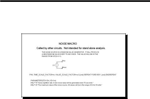
NOISE
This macro implements a random noise generator to produce a noisy time-domain waveform.
Figure 21-13 NOISE macro equivalent circuit
The parameter definitions are as follows:
Parameter |
Definition |
TS |
Noise repetition rate. A new noise value will be generated |
|
every TS seconds. |
VS |
The maximum value of the noise source. All values will |
|
be in the range of 0.0 to VS volts. |
344 Chapter 21: Analog Behavioral Building Blocks
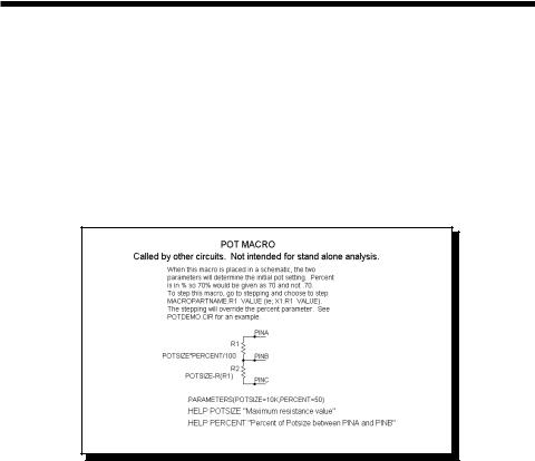
POT
This macro implements a potentiometer using several resistor value expressions. The two parameters determine the initial pot setting. Percent is in % so 70% would be given as 70 and not .70.
To sweep the pot wiper arm, step the Value field of the macro resistor R1 from the Stepping dialog box. The stepped value will override the default percent parameter. See POTDEMO.CIR for an example.
Figure 21-14 POT macro equivalent circuit
The parameter definitions are as follows:
Parameter |
Definition |
Potsize |
Maximum resistance value |
Percent |
Percent of Potsize between PINA and PINB |
See the circuit POTDEMO for an example of the use of this macro.
345
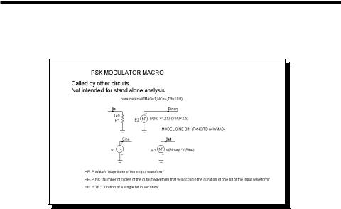
PSK
This is a phase-shift keyer.
Figure 21-15 PSK macro equivalent circuit
The parameter definitions are as follows:
Parameter |
Definition |
WMAG |
Magnitude of the output waveform |
NC |
Number of cycles of the output waveform that will occur |
|
in the duration of one bit of the input waveform |
TB |
Duration of a single bit in seconds |
See the circuit PSK2 for an example of the use of this macro.
346 Chapter 21: Analog Behavioral Building Blocks