

Micro-Cap v7.1.6 / RM
.PDFDC analysis variables
Both analog and digital variables are available in DC analysis. They include:
•Voltage: If the mouse probes on a digital node, the digital state of the node is selected. If the mouse probes on an analog node, its node voltage is selected. If the mouse probes on the shape of a two-lead component, the voltage across the component is selected. If the mouse probes between two leads of a three or four lead active device, the lead-to-lead differential voltage is selected. Hold Shift down and probe on two nodes to get differential voltage.
•Current: If the mouse probes on a digital node, the digital state of the node is selected. If the mouse probes on the shape of a two-lead component, the current through the component is selected. If the mouse probes on a lead of a three or four lead active device, the current into the lead is selected.
•Power: If the mouse probes on a component, it plots the power dissipated (PD), generated (PG), or stored (PS) in that component. If the component has more than one of these, a list appears allowing selection. Clicking off a component lets you select one of the total power terms, PGT (total generated power), PST (total stored power), or PDT (total dissipated power).
•Linear: This selects a linear scale.
•Log: This selects a log scale.
The default horizontal variable is the value of the specified Variable 1 of the DC Analysis Limits dialog box. For example, if the source is a voltage source, the horizontal value is the voltage across the source, or if the source is a current source, the horizontal value is the current through the source.
This default can be changed through the Plot item in the Properties dialog box. The Properties dialog box is invoked by clicking in the Probe plot, then pressing F10. A plot must be present before an X variable change can be made.
217

Probe analog variables
The Horizontal and Vertical menus are used to select the curve variables and operators which will be displayed by Probe. The curves displayed for each variable or operator are dependent upon the component selected. The variables and operators are shown in the following tables.
Component Variables
C om ponent |
Volt age |
C urrent |
C apac ita nce / |
C harge / F lux |
Ene rgy / P ow er |
Ene rgy / P ow er |
Ene rgy / P ow er |
|
Inducta nce |
G enerated |
S tored |
D issipa ted |
|||||
|
|
|
|
|||||
|
|
|
|
|
|
|
|
|
S ources |
V |
I |
N A |
N A |
EG / P G |
N A |
N A |
|
R esistor |
V |
I |
N A |
N A |
N A |
N A |
ED / P D |
|
|
|
|
|
|
|
|
|
|
C apac itor |
V |
I |
C |
Q |
N A |
ES / P S |
N A |
|
|
|
|
|
|
|
|
|
|
Inductor |
V |
I |
L |
X |
N A |
ES / P S |
N A |
|
|
|
|
|
|
|
|
|
|
D iode |
V |
I |
C |
Q |
N A |
ES / P S |
ED / P D |
|
|
|
|
|
|
|
|
|
|
Transmission Line |
VA P, VA M, V B P |
IA P, IAM |
N A |
N A |
N A |
N A |
N A |
|
V B M |
IB P, IB M |
|||||||
|
|
|
|
|
|
|||
|
|
|
|
|
|
|
|
|
|
V B , V C , V E, |
|
|
|
|
|
|
|
B JT |
V B E, VB C , V EB |
IB , IE, IC |
C B E, C B C |
Q B E, QB C |
N A |
ES / P S |
ED / P D |
|
|
V EC , VC B , V C E |
|
|
|
|
|
|
|
|
|
|
|
|
|
|
|
|
|
V B , V C , V E, VS , |
|
|
|
|
|
|
|
|
V B E, VB C , V B S |
IB , IE, IC |
C B E, C B C |
Q B E, QB C |
|
|
|
|
B JT4 |
V EB VE C , VES |
N A |
ES / P S |
ED / P D |
||||
IS |
C C S |
Q C S |
||||||
|
V C B, V C E, V C S |
|
|
|
||||
|
|
|
|
|
|
|
||
|
V SB , V SE , VS C |
|
|
|
|
|
|
|
|
V G, V S, V D , V B , |
|
|
|
|
|
|
|
|
V GS , VG D , VG B |
IG , IS , ID |
C G S, C G D |
Q GS , QG D |
|
|
|
|
M OS FE T: LEV 1-3 |
V DS , VD G , VD B |
C G B, C B D |
Q GB , Q B D |
N A |
ES / P S |
ED / P D |
||
IB |
||||||||
|
V SG , VS D , VS B |
C B S |
Q B S |
|
|
|
||
|
|
|
|
|
||||
|
V B G, V B D, V B S |
|
|
|
|
|
|
|
|
|
|
|
|
|
|
|
|
|
V G, V S, V D , V B , |
|
|
|
|
|
|
|
|
V GS , VG D , VG B |
IG , IS , ID |
|
|
|
|
|
|
M OS FE T:LEV 4,5,8 |
V DS , VD G , VD B |
N A |
N A |
N A |
N A |
ED / P D |
||
IB |
||||||||
|
V SG , VS D , VS B |
|
|
|
|
|
||
|
|
|
|
|
|
|
||
|
V B G, V B D, V B S |
|
|
|
|
|
|
|
|
|
|
|
|
|
|
|
|
O PA MP |
V P, VM , V OU T, |
N A |
N A |
N A |
N A |
N A |
N A |
|
V PM , VC C , V EE |
||||||||
|
|
|
|
|
|
|
||
|
|
|
|
|
|
|
|
|
|
V G, V D, V S , |
|
|
|
|
|
|
|
JFE T |
V GS , VG D , VS G |
IG , ID , IS |
C G S, C G D |
Q GS , QG D |
N A |
ES / P S |
ED / P D |
|
|
V SD , VD G , VD S |
|
|
|
|
|
|
|
|
|
|
|
|
|
|
|
|
|
V G, V D, V S , |
|
|
|
|
|
|
|
G aA sF ET |
V GS , VG D , VS G |
IG , ID , IS |
C G S, C G D |
Q GS , QG D |
N A |
ES / P S |
ED / P D |
|
|
V SD , VD G , VD S |
|
|
|
|
|
|
|
|
|
|
|
|
|
|
|
Va riable s that are mere pe rmuta tions of the le ads are not shown. F or exam ple C G S a nd C SG produce the sa me plot as do Q G S and Q S G.
Table 14-1 General syntax for Probe variables
Resistance is available only for resistors. Inductance, B field, and H field are available only for inductors.
218 Chapter 14: Probe
Probe regions
When probing for node voltages or digital states, you click the mouse on one of the round dots shown on the node, or on any portion of any wire connecting to a node. If there is more than one dot on a node, it doesn't matter which you pick.
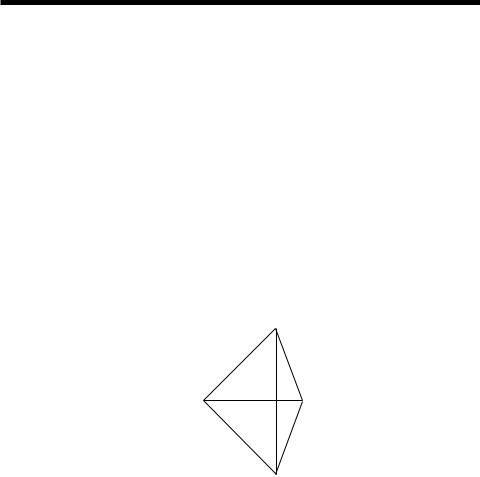
Probe can plot many internal device variables. For example, the internal charge and capacitance of a MOSFET (Level 1-3 only) can be accessed. The probe regions for devices with three or more pins are more complicated than for nodes and other devices. For example, the variable selected for a transistor is determined by the nearest device pin line segment. These line segments are illustrated below for the case of a MOSFET. When the mouse is clicked near a device, the distance from each line segment to the point where the mouse is clicked is determined. The closest line segment determines the two leads. The Vertical and Horizontal menu choices determine the variable type.
Drain to Gate |
|
|
|
|
|
|
|
|
Drain to Body |
|
|
|
|
|
|
|
|
|
|||
Gate to Source |
|
|
|
|
|
|
|
Drain to Source |
||
|
|
|
|
|
|
|||||
|
|
|
|
|
|
|
Source to Body |
|||
|
|
|
|
|
|
|
||||
Gate to Body |
|
|
|
|
|
|
|
|
|
|
|
|
Figure 14-1 MOSFET line segment diagram |
||||||||
|
|
|
||||||||
219

Probing a SPICE file
MC7 can also probe SPICE files. Clicking on two-terminal devices like sources, resistors, and diodes plots the voltage across or current through the device, depending upon whether the Vertical option is set to Voltage or Current.
Clicking on three-terminal devices, presents a dialog box where you can select the desired voltage or current variable.
Clicking on a node number plots the node voltage.
220 Chapter 14: Probe

Chapter 15 |
Stepping |
What's in this chapter
Stepping is the process of varying a parameter value to see its effect on circuit behavior. Transient, AC, and DC analysis all provide the capability of stepping parameter values.
This feature cannot be used simultaneously with Monte Carlo analysis. If both are enabled, MC7 will enable the last one turned on by the user, and disable the other.
Stepped waveforms are plotted on the same graph. To distinguish one from the other, use Cursor mode and the UP CURSOR ARROW and DOWN CURSOR ARROW keys to switch between branches. As the cursor keys change the selected branch (step value) of the waveform, the window title changes showing the value of the stepped parameter(s). You can also label the individual branches and use the mouse or the Go To Branch feature to select individual branches.
Features new in Micro-Cap 7
•Text stepping using symbolic parameters and the list method.
•Stepping symbolic parameters created with .PARAM.
•Ability to identify curve branches by labeling them and by selecting them with the ALT key and a mouse click or the Go To Branch feature.
221

How stepping works
Stepping systematically alters the value of one or more parameters of one or more components and then runs the analysis, drawing multiple branches for each curve. Earlier versions of the program placed restrictions on changing some variables, such as the model level and parasitic resistances. Most parameter types can now be stepped, including attribute parameters like the resistance of a resistor, model parameters like a transistor beta, and symbolic parameters created with a
.define or a .param command. If the parameter changes the equation matrix, MC7 simply recreates the equations. For each parameter set, a run is made and the specified waveforms plotted.
With parameter stepping enabled, 3D plots can be used to display performance function dependence on parameter values.
What can be stepped?
There are three basic types of variables that can be stepped:
Attribute parameters
Model parameters
Symbolic parameters (those created with a .DEFINE statement)
Some components such as the simple dependent sources, IOFI, IOFV, VOFI, and VOFV, are characterized by a single attribute parameter called 'VALUE'. In this type of component, this is the only parameter that can be stepped.
Some components have only model parameters, and these are the only parameters that can be stepped.
Some components have both attribute and model parameters and both types of parameters can be stepped.
Symbolic parameters used in model statements or attributes can be stepped.
Using a symbolic variable, you can also step text using the list option. This is handy for changing models, stimulus files, or other text-based parameters.
222 Chapter 15: Stepping
The Stepping dialog box
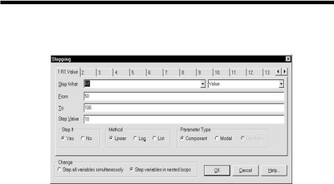
Parameter stepping is controlled by the Stepping dialog box. It looks like this:
Figure 15-1 The Stepping dialog box
The dialog box is divided into several areas:
• Parameter Panels
The dialog box provides tabs for up to twenty parameters, although two or three is a practical maximum. Each tab accesses a panel which controls a single parameter. Stepping for each parameter is enabled when its Step It option is set to Yes.
•Step It: Set this option to Yes to enable stepping for the parameter.
•Step What
The left Step What list box in each parameter panel specifies the name of the model parameter, component, or symbolic variable value to be stepped. Since dissimilar parts may share the same model name, the electrical definition is shown along with the name. Clicking on the list box displays a list of the items available for stepping. To select one, click on it. The right Step What list box in each panel specifies the name of the parameter to be stepped. Clicking on the list box displays a list of the available parameters. To select a parameter, click on it.
•From: This field specifies the starting value of the parameter.
•To: This field specifies the ending value of the parameter.
223
•Step Value: This field specifies the step value of the parameter.
•Method: The Method option in each panel controls how the Step Value affects the parameter value.
•Linear: Linear stepping adds the Step Value.
•Log: Log stepping multiplies by the Step Value.
•List: List stepping lets you enter a comma-delimited set of specific values in the From field.
•Parameter Type: This option in each panel specifies whether the Step What field refers to a model, component, or symbolic name.
•Component: This is used for passive parameter values, as for example, the resistance of a resistor.
•Model: This is used for model parameters, as for example, the BF of a BJT, or a delay parameter for a digital device.
•Symbolic: Symbols are variables created with a .DEFINE or a .PARAM statement. They can be used in component value parameters or in model parameters. Stepping them is a powerful way of controlling many parameter values. For example, you can control the W and L of many MOSFET devices with this:
.DEFINE W1 2U
.DEFINE L1 0.3U
.MODEL NM1 NMOS (W=W1 L=L1...)
This lets you selectively step only the W and L of the devices that use the symbols W1 and L1.
You can step an individual instance or all instances of a model parameter. In Component mode, stepping affects one parameter of one device only if the PRIVATEANALOG and PRIVATEDIGITAL options (Global Settings) are enabled. In Model mode, stepping affects one parameter of all devices that use that model name. This is true regardless of the state of the PRIVATEANALOG or PRIVATEDIGITAL flags.
224 Chapter 15: Stepping
• Change: The Change option only comes into play if you are stepping multiple parameters. It controls whether the parameter changes are to be nested or simultaneous.
•Step all variables simultaneously: In this type of change, all parameters change value simultaneously, so you get a small set of matched parameter values.
•Step variables in nested loops: In this type of change, each parameter changes independently, so you get all combinations of the specified values.
For example, suppose you step L1 through the values 1u and 2u and you step C1 from 1n to 2n. Simultaneous stepping, will produce two runs, and nested stepping will produce four runs as shown below.
Nested |
Simultaneous |
L1=1u C1=1n |
L1=1u C1=1n |
L1=1u C1=2n |
L1=2u C1=2n |
L1=2u C1=1n |
|
L1=2u C1=2n |
|
Simultaneous stepping requires an equal number of steps for each parameter. If the parameter panels specify different numbers of steps, an error message will be issued. Use nested stepping when you want all combinations of parameter variation. Use simultaneous stepping when you want only specific combinations.
•OK: This button accepts the changes made and exits the dialog box.
•Cancel: This button ignores any changes and exits the dialog box.
•Help: This button accesses the Help system.
225
Public vs. private libraries
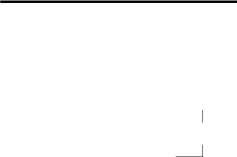
To illustrate the stepping possibilities with the four combinations of public or private libraries and component or model stepping, imagine a circuit with two transistors, each having a MODEL attribute of "2N2903".
This circuit uses two transistors with component names Q1 and Q2. They both use the 2N2903 model. This diagram illustrates the four possibilities.
|
Private Models |
Public Models |
|||||
Component Mode Stepping |
|
|
|
|
|
|
|
Q1 |
|
2N2903 |
|
Q1 |
|
2N2903 |
|
|
|
|
|||||
Case 1: Step Q1.BF |
|
|
|
|
|
|
|
Model Mode Stepping
Case 2 : Step 2N2903.BF
Q2 |
|
2N2903 |
Q2 |
|
|
|
|
|
|
|
|
||||
|
|
|
|
|
|
|
|
Q1 |
|
2N2903 |
Q1 |
|
|
2N2903 |
|
|
|
|
|||||
Q2 |
|
2N2903 |
Q2 |
|
The shaded models are changed by stepping. In case 1, we are stepping Q1.BF. In this case we step the model that Q1 points to. When the libraries are private, then the model pointed to by Q1 would be stepped and that pointed to by Q2 would not be stepped. They point to distinct model locations, even though they use the same model name. When the libraries are public, stepping the model pointed to by Q1 also steps the model pointed to by Q2 since they point to the same model location.
In case 2, we are stepping 2N2903.BF. In this case we step all of the instances of the 2N2903 model. It doesn't matter whether models are private or public, since all instances of the model are changed.
Only component stepping and private libraries selectively step individual instances of model parameters. All other cases step all instances of model parameters.
226 Chapter 15: Stepping