

Basic_Electrical_Engineering_4th_edition
.pdf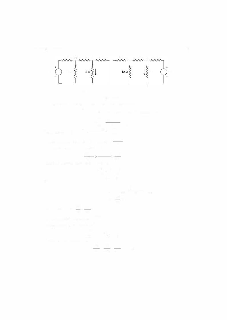
1 36 |
ELECTRICAL ENGINEERING |
2.7THEVENIN'S THEOREM
This theorem is most useful as many a times we may be interested in the current/voltage in a part ofthe otherwise a much more complex network. We may not be interested in the current/ voltage through all the branches of the network e.g. determining fault current in a particular branch of a complex power system or finding out the value of load resistance for an electronic circuit which will result in the maximum power transferred to this load.
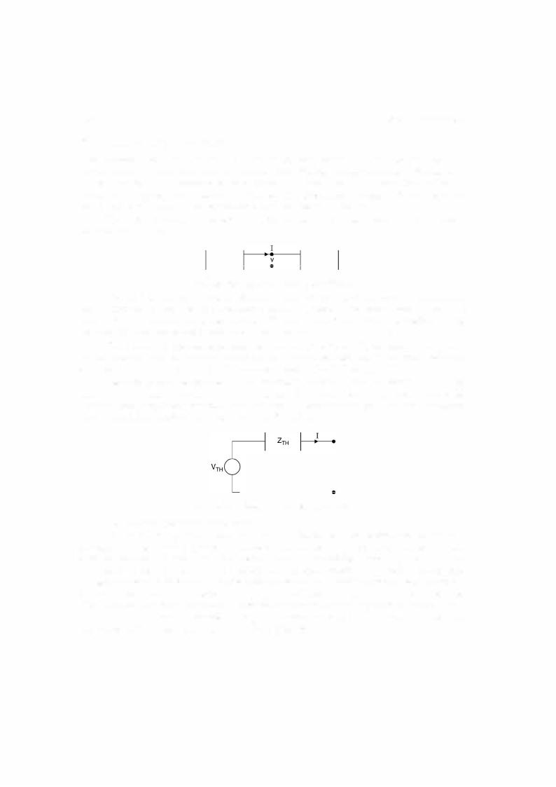
Thevenin's theorem can be explained with the help oftwo networks A and B connected as shown in Fig. 2.8.
A B
Fig. 2.8 Two networks A and B connected.
The original network can be considered as a combination and connection of networks A and B. Network A contains linear elements which may have initial conditions. It may also have an independent and dependent sources. However, there is no mutual magnetic coupling between the networks A and B nor does a controlled source in A couple to B.
For network B, the elements need not necessarily be linear. These could be non-linear or time varying or both. However, in our analysis we will assume that the network elements are linear and many a times this will be a single branch (load) of the network.
Network A is to be replaced by an equivalent network under the condition that the current I and voltage Videntified in the Fig. remain invariant when the replacement is made. Thisamounts to replacing networkA by an equivalent Thevenin's voltage source and an equiva lent Thevenin's series impedance as shown in Fig. 2.8 (a).
v
Fig. 2.8 (a) Thevenin equivalent of Fig. 2.8.
The following procedure is followed :
To determine VTH we remove the network B (could be a load resistor or the element through which current is required) and solve the networkA to find out voltage across the open circuited terminal. This voltage is the Thevenin's equivalentvoltage source VTH" Also zeq is the impedance as seen in the network between the two open circuited terminals replacing the voltage sources bytheirequivalent series impedances and the current sourcesbytheir equivalent shunt admittances. The impedance as seen is known as Thevenin's equivalent series impedance. While finding Thevenin's equivalent, dependent sources continue to operate in the network.
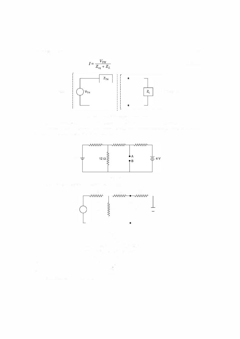
If ZL is the load impedance and zeq the Thevenin's equivalent series impedance (Fig. 2.9) the current through the load impedance is given by
NETWORK THEORY |
|
1 37 |
------------------------, |
II |
...(2.14) |
Network A |
- - - - - - - - - - - - - - - - - - - - - - IIIIIIIIIIIIIIII! |
Network B |
L-- -------- - - - - - - -------- |
_ _ _ _ _ _ _ _ _ _ _ _ _ _ _ _ _ _ _ _ _ _ J |
|
Fig. 2.9 Thevenin's equivalent with load.
A few examples will further illustrate the application of Thevenin's theorem.
Example 2.10. Determine the current through 2 .Q resistor connected between A and B in the circuit shown using Thevenin theorem.
or or
or
2 Q |
1 Q |
3 Q |
2 V
|
Fig. E2.10 |
|
|
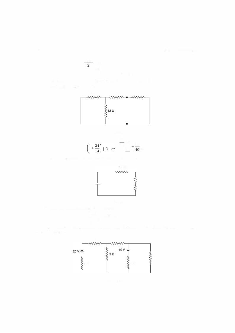
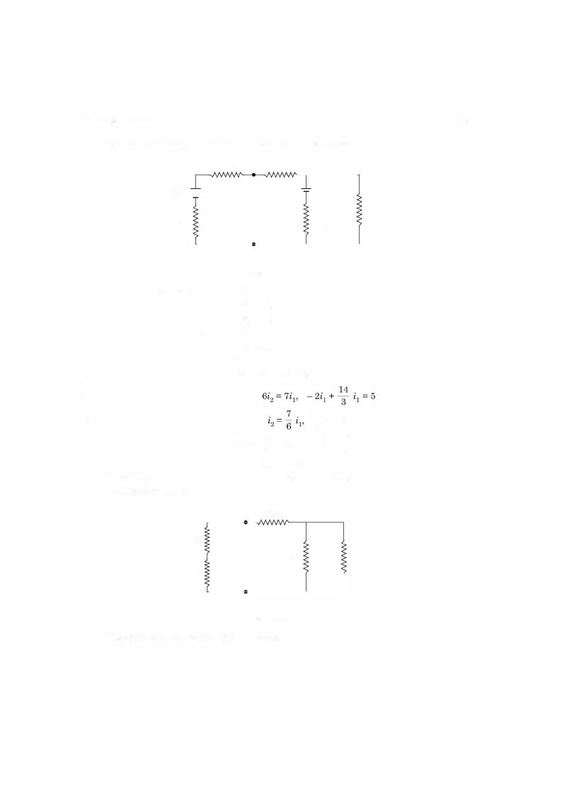
Solution: To obtain VTH refer Fig. below: |
|
|
|
2 Q |
1 Q |
A |
3 Q |
2 V |
. |
) |
12 Q |
i2) |
-=- |
4 |
v |
11 |
|
|
B
Fig. E2.1 0.1
2il + 12(il + i2) = 2, 4i2 + 12il + 12i2 = 4
14i1 |
|
+ |
l2i2 |
== |
42 |
|
or |
7i1 |
+ |
6i2 |
= |
1 |
|
+ |
|
or |
+ |
= |
|||||||||
12i1 |
|
+16i2 |
= |
3il |
+ |
4i2 |
3i1 |
|
4i2 |
|
1 |
||
7il |
|
6i2 |
= |
|
|
|
|
|
|
||||
|
|
|
4il |
|
- |
2i2 |
|
|
|
|
|
|
|
|
|
|
. |
= |
i : i |
|
|
|
|
|
|
||
|
|
|
i1 |
- |
|
|
|
|
|
|
|
|
|
|
|
|
|
|
2 |
|
|
|
|
|
|
||
...(1)
Substituting in (1) we have
140 |
ELECTRICAL ENGINEERING |
2 Q
12.5 v |
2 Q |
|
Fig. |
E2. 11 .3 |
|
J |
12.5 |
125 |
A |
= -- = 3. |
|||
AB |
4 |
|
|
|
|
|
|
2.8NORTON'S THEOREM
Norton's theorem is dual of Thevenins theorem and can be stated as follows:
It states that any two terminal linear network can he replaced hy an equivalent network consisting of a current source 10 in parallel with a network ofimpedance Z0. The impedance is same as that found for Thevenins equivalent and l0 is the current between the two terminals when these terminals are short circuited. The following example will further clarify the con cepts associated with the theorem.
E |
Determine the current through the resistance |
R |
L = 1, 2, 5 Q for the net |
||
Example 2.12. |
2.12. Using Thevenin's theorem. |
|
|
||
work shown in Fig. |
|
|
|
||
|
4 0 |
5 0 |
A |
|
|
|
40 V .=.. 1 |
6 0 |
B }' |
|
|
Fig. E2.12
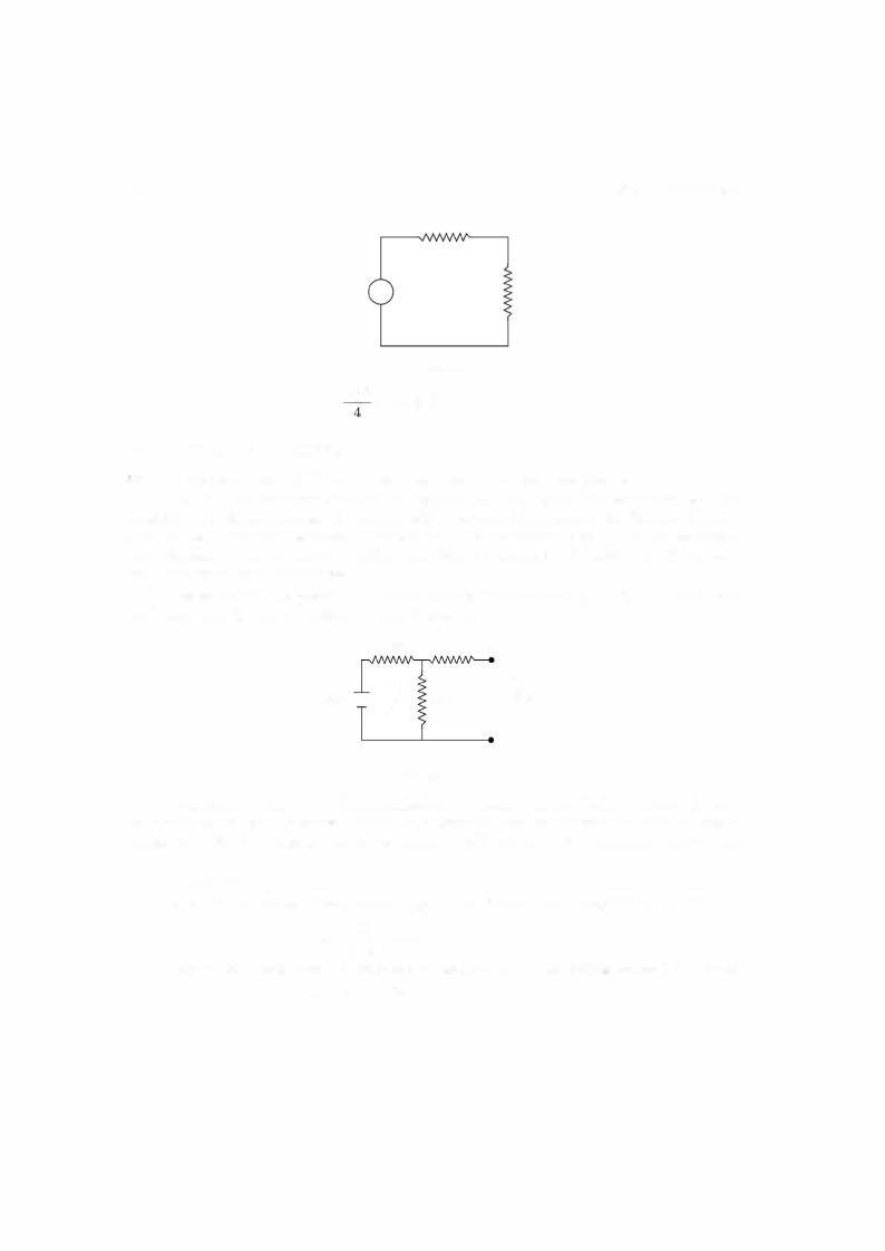
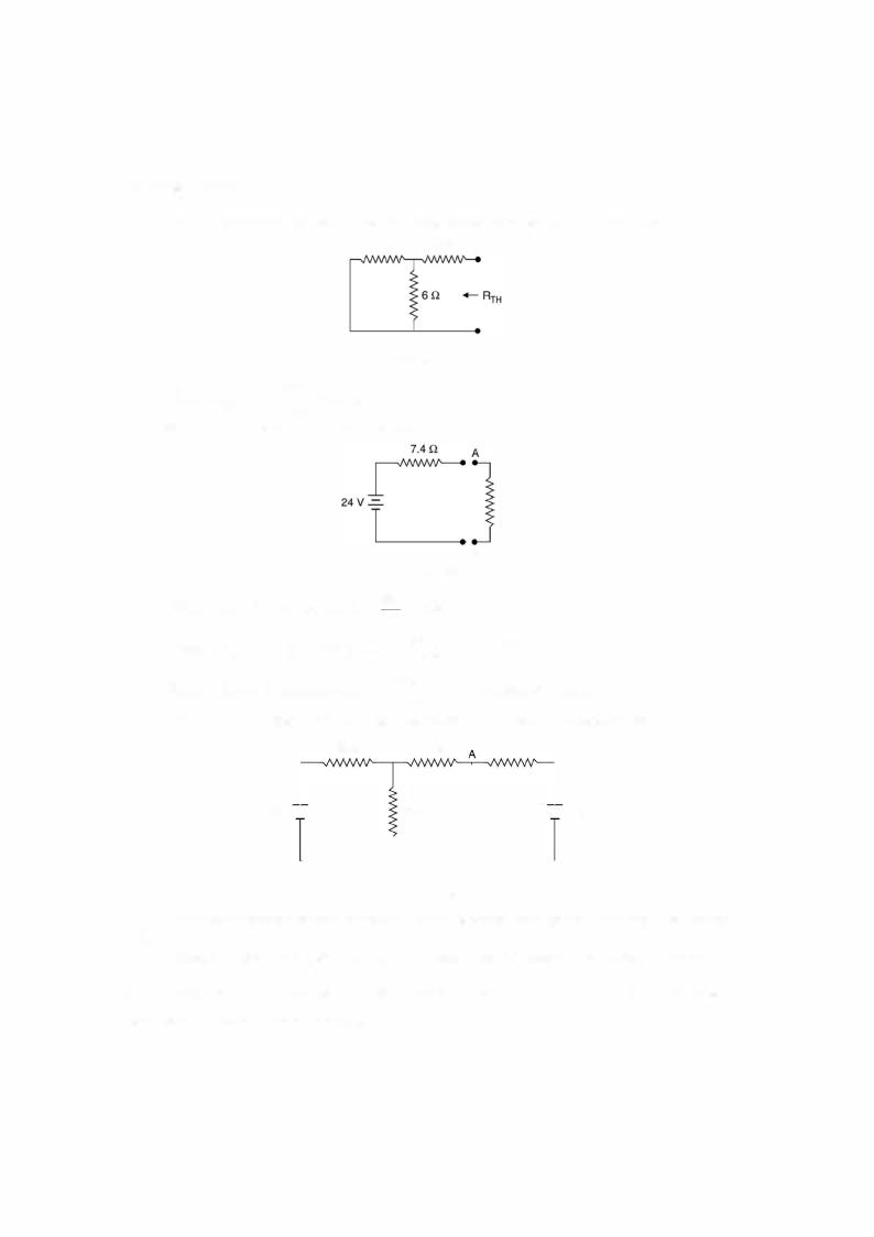
Solution: We remove RL from the network and obtain the equivalent Thevenin's volt age source i.e. the voltage across AB when RL is removed and the Thevenin's equivalent series resistance which is the resistance as seen between AB into the network shorting the voltage sources.
To find out V TH |
|
|
|
|
|
|
|
When RL is removed, there is one closed loop and hence the current in the loop is |
|||||||
|
= __±Q_ |
= 4A |
AB |
|
|
|
|
i.e. |
|
4 + |
= 24V |
|
6 Q |
|
|
VrH = 6 x 6 |
|
|
|||||
Now when RL is removed,i |
voltage across terminals |
|
is the voltage across |
|
resistor |
||
|
|
4 |
|
|
|
|
|
1 42 |
ELECTRICAL ENGINEERING |
226
|
|
|
|
2 + |
12 |
38 |
|
|
= |
|
|
|
|
|
|
|
13 |
|
26 |
12 |
12 |
|
|||
|
|
|
|
|
|
|
|
|||||
|
|
|
|
|
|
|
|
|
||||
Therefore current through |
|
will be |
38 x |
13 |
19 |
A |
||||||
so total current is 34 x |
12 |
= |
1 12 |
AAB |
|
|
|
|
|
|
||
19 |
57 |
|
|
|
|
|
|
|
||||
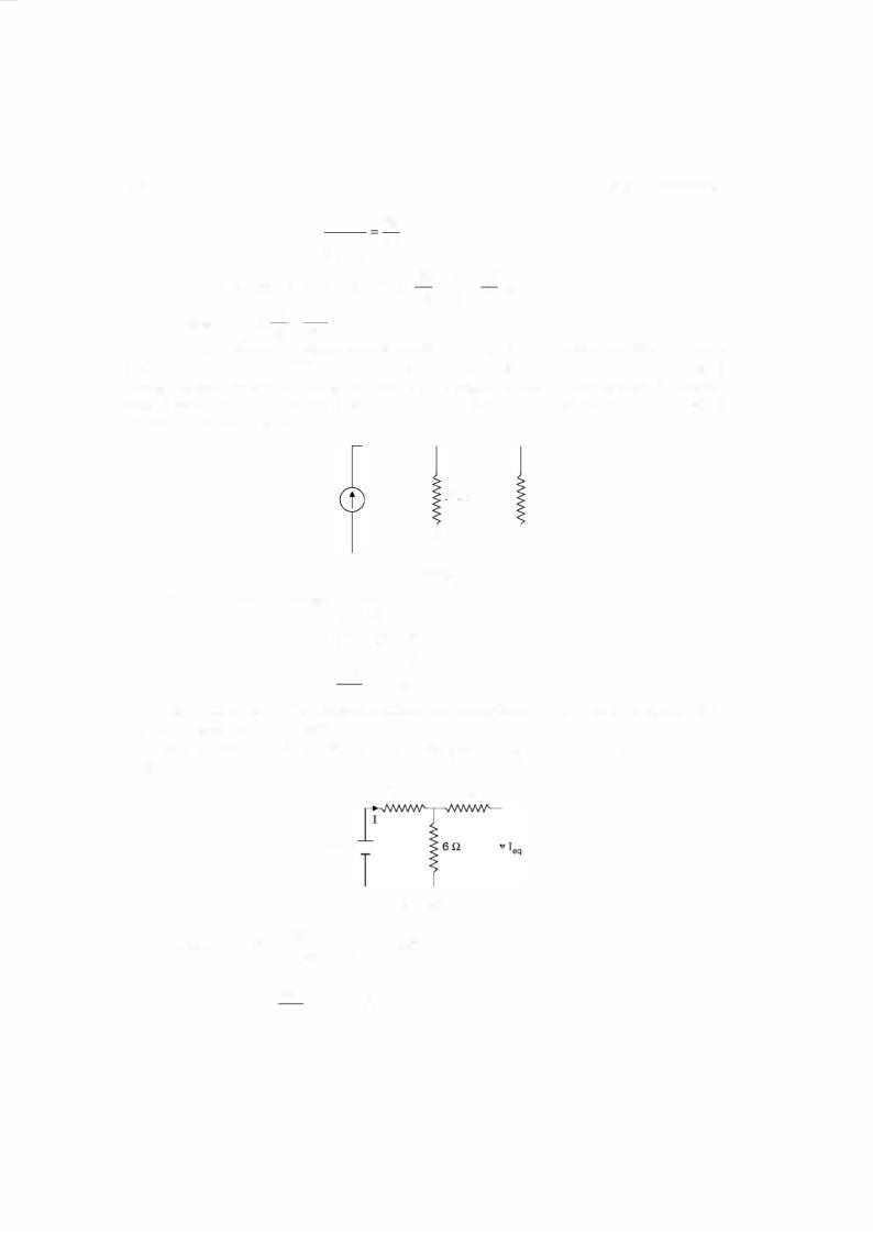
So that Norton's equivalent current source is 112/57 A The Norton's equivalent imped ance is same as in case of Thevenins equivalent impedance except that it is to be connected across the current source. Along with this the resistance through which current is required should be connected across the current source. This forms the complete equivalent Norton's circuit and is drawn here.
|
|
|
|
1.571._gA |
|
|
|
|
57 |
Q |
2 Q |
|
|
|
|
|
|
|
|
|
|
40 |
|
||
|
|
|
|
|
|
Fig. E2.1 3.1 |
|
|
|
|||
|
Current through 2 Q resistor is |
|
|
1 |
|
|
|
|||||
|
|
|
|
112 |
57 |
|
|
|
|
|
||
|
|
|
|
- - x - x |
--- |
|
|
|
||||
|
|
|
|
For the network |
|
|
|
|
||||
|
|
|
|
57 |
40 |
|
57 |
|
+ 2 |
|
|
|
|
|
|
|
= 112 |
|
|
40 |
|
|
|
|
|
|
|
|
|
= 0.82 A |
|
|
|
|
|
|||
|
|
|
|
137 |
|
|
|
|
in Example 2. 12, determine the current in |
RL |
||
|
Example |
To obtain the Norton'sshown |
||||||||||
used2, |
5 Q |
using Norton's theorem. |
|
|
|
|
|
|
|
|
||
= 0, |
|
|
|
equivalent current source, following circuit would be |
||||||||
|
Solution: |
|
|
|||||||||
|
|
|
|
|
|
4 Q |
|
5 0 |
|
|
||
40 v - = -
Fig. E2.14
Current I = ------40 = 74440 =W5-.946 A
4 + -
11
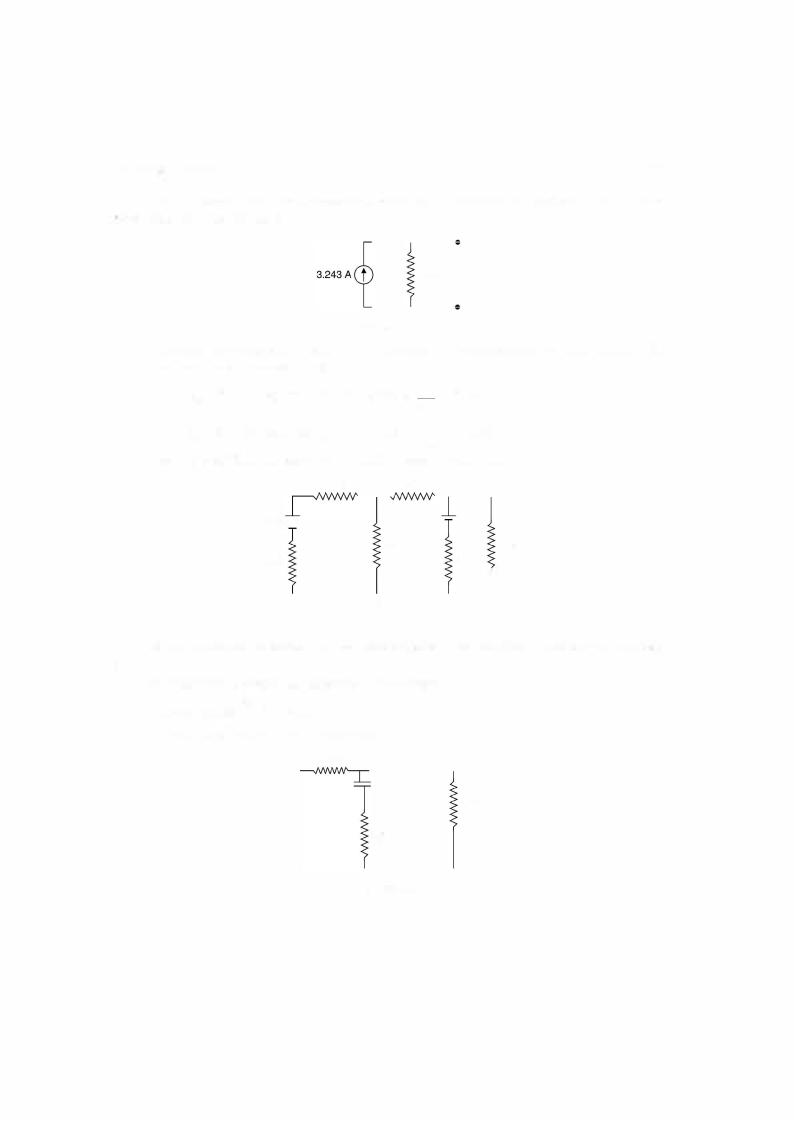
Hence Ieq = 440 x = 3.243 74 11
NETWORK THEORY |
1 43 |
The equivalent Norton's resistance is same as in Thevenin's equivalent i.e. 7.4 n. The Norton's equivalent circuit is
7.4 Q
|
Fig. E2.1 4.1 |
|
|
|
Now current through RL whenRL = 0. Obviously the total current will flow through RL |
||||
and no current through resistance 7.4 |
nL = 3.243 |
|
|
|
L = 2!.1, current through |
7.4 |
= 2.55 A |
||
9.4 |
||||
R |
R |
|
|
|
RL = 5 n current through RL = 3.243 x |
7 4 |
|
= 1.935 A |
|
|
|
12.4 |
|
theorem. |
Example 2.15. Solve example 2.11 using Norton'sx · |
||||
2 Q |
A |
2 Q |
20 v - = - |
|
1 0 V |
|
|
|
|
|
2 Q |
2 Q |
|
4 Q |
4 Q
B
Fig. E2. 15
AB. Solution: Shorting branchAB and using superposition principle to find current through
20 Volts in the circuit and shorting 10 volt source The current is 420 A = 5 A
10 volts in the circuit and shorting 20 V
2 0
1 0 v
4 Q
4 U
Fig. E2.1 5.1