
Finkenzeller K.RFID handbook.2003
.pdf
12.2 CONTACTLESS SMART CARDS |
333 |
|
Filling |
|
|
Overlay foil |
|
|
Stamped out foil |
|
|
Connection |
Antenna |
|
method |
Carrier foil |
|
|
||
Contactless |
Overlay foil |
|
chip module |
||
|
Figure 12.4 Foil structure of a contactless smart card
process (see Section 12.2.3) from collapsing around the chip module and to give a smooth and even card surface (Haghiri and Tarantino, 1999).
12.2.1 Coil manufacture
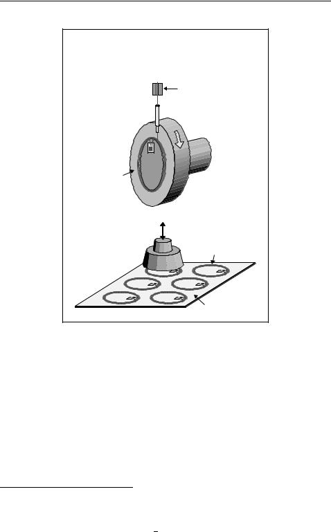
Winding In the winding technique the transponder coil is wound upon a winding tool in the normal way and affixed using baked enamel. After the chip module has been welded onto the antenna, the semi-finished transponder is placed on the inlet sheet and mechanically affixed using cemented joints (Figure 12.5).
For contactless smart cards in the frequency range <135 kHz the winding technique is the only procedure that can be used for the manufacture of transponder coils due to the high number of windings (typically 50–1500 windings).
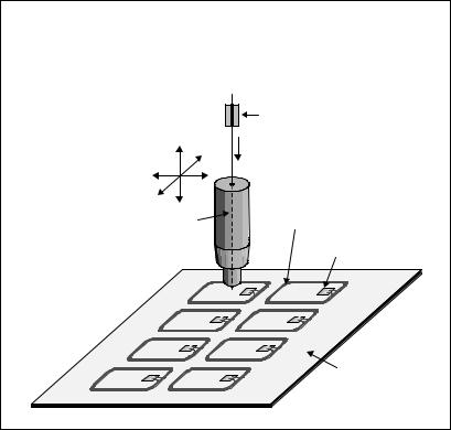
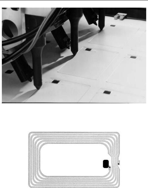
Embedding Inlet manufacture using the embedding technique (Figures 12.6 and 12.7) is a relatively new procedure that is nevertheless increasing significantly in importance. In this technique, the chip module is first affixed in its intended location on a PVC foil. The wire is then embedded directly into the foil using a sonotrode. The sonotrode consists of an ultrasonic emitter with a passage in its head through which the wire is guided onto the foil. The ultrasound emitter is used to locally heat the wire to such a degree that it melts into the foil and is thus fixed in shape and position. The sonotrode is moved across the inlet foil in a similar manner to an X–Y plotter, while the wire is fed through, so that the transponder can be ‘drawn’ or embedded. At the start and the end of the coil a spot welding machine is used to make the electrical connection to the transponder module.
Screen printing The screen printing technique is a common printing technique in industrial production and is used, for example, in the production of wallpaper, (PVC) stickers, signs, and also in textile printing. A screen mesh made of synthetic or natural fibres or metal wires is stretched over a frame. The fineness of the screen mesh and the strength of the fibres are selected on the basis of the resolution of the print and the viscosity of the paint. The template is applied to the screen mesh manually or photomechanically. The actual print motif, in our case a coil, remains free. The template material may, for example, be a light-sensitive emulsion that is applied to the screen. If this coated screen is illuminated through a printing film, the emulsion hardens at the illuminated points. The points that have not been illuminated are washed out with water. Colour drawn over the screen with a rubber squeegee is pressed through these
334 12 THE MANUFACTURE OF TRANSPONDERS AND CONTACTLESS SMART CARDS
AmaTech 
AmaTech coil winding principle |
with interconnection |
of coil wire ends with IC Module |
Coil winding tool |
Heat & Force |
LF & HF wound coil |
Inlet sheet |
DF / 18.Nov.1996 |
Figure 12.5 Production of a semi-finished transponder by winding and placing the semifinished transponder on an inlet sheet (reproduced by permission of AmaTech GmbH & Co. KG, Pfronten)
open points and onto the chosen material. The screen is raised and the print is complete. All structures have a raster pattern due to the screen mesh. The elasticity of the screen guarantees extremely high accuracy.
This procedure is used to print a coil of any shape directly onto an inlet foil (Figure 12.8). So-called polymer thick film pastes (PTF) are used as the ‘printing ink’. These consist of the powder of a conductive material (silver, copper, graphite), a light solvent, and a resin as the fixing agent. After drying out, a conductive film is left behind in the printed shape on the inlet. The surface resistance RA1 of the film is around 5–100 / 1 and falls back to around 50–80% after lamination, since the
1 The surface resistance RA of a quadratic conductive layer is dependent only upon the specific conductivity
κ and the thickness d of the conductive layer and is quoted in / : RA = |
1 |
= |
ρ |
|
κ d |
d |
|
||
To determine the conductive track resistance, the surface resistance is multiplied· |
by the ratio of length |
|||
l to breadth b of the conductive track: R = RA · l b
12.2 CONTACTLESS SMART CARDS |
335 |
AmaTech 
AmaTech wire embedding principle |
|
with interconnection of coil wire ends with IC module |
|
Z |
|
|
Y |
X |
|
Sonotrode |
HF embedded coil |
|
|
|
Chip module |
|
Inlet sheet |
DF / 18.Nov.1996 |
|
Figure 12.6 Manufacture of an inlet sheet using the embedding principle (reproduced by permission of AmaTech GmbH & Co. KG, Pfronten)
effect of heat and pressure during the lamination process increases the partial contact between the individual grains of the mixed (metal) powder.
Depending upon layer thickness, conductor track width, and number of windings, a typical coil resistance of 2–75 (smart card with 2–7 windings) can be achieved. Due to the broad conductor track path (i.e. limited number of windings) this technology is, however, only suitable for frequency ranges above 8 MHz. Due to cost benefits, printed coils are also used for EAS tags (8 MHz) and Smart Labels (13.56 MHz).
Etching The etching technique is the standard procedure used in the electrical industry for the manufacture of printed circuit boards. Inlet foils for contactless smart cards can also be manufactured using this procedure. In a special procedure a full-sized copper foil of 35 µm to 70 µm thickness is first laminated onto a plastic foil without the use of adhesive. This copper layer is now coated with a light-sensitive photo-resist, which is dried and then illuminated through a positive film. The picture on the positive film is the subsequent form of the coil. In a chemical developing solution the illuminated points of the photo-resist are washed out, so that copper is once again exposed at these points. In the subsequent etching bath, all areas that are no longer covered by photoresist are etched free of copper, so that finally only the desired coil form remains. The

12.2 CONTACTLESS SMART CARDS |
339 |
|
|
|
|
|
|
|
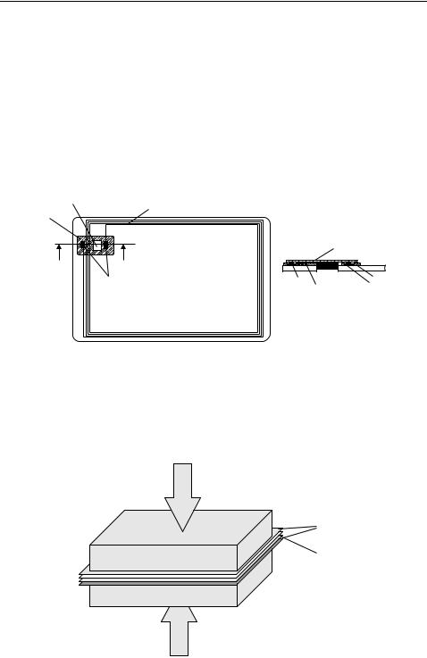
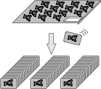
Figure 12.12 After the cooling of the PVC sheets the individual cards are stamped out of the multi-purpose sheets
of heat, the foils are brought into a soft elastic state at high pressure (approximately 100–150 ◦C). This ‘bakes’ the four sheets to create a permanent bond (Figure 12.11).
After the lamination and cooling of the laminated PVC foils, the individual smart cards are stamped out of the multi-purpose sheet (Figure 12.12). A subsequent functional test ensures the quality of the cards before these can be sent to the customer.
RFID Handbook: Fundamentals and Applications in Contactless Smart Cards and Identification, Second Edition
Klaus Finkenzeller Copyright 2003 John Wiley & Sons, Ltd.
ISBN: 0-470-84402-7
13
Example Applications
13.1Contactless Smart Cards
The first plastic cards appeared in the USA as early as the beginning of the 1950s, when cheap PVC replaced cardboard. In the years that followed, plastic credit cards became widespread. Incidentally, the first credit card was issued by Diners Club in 1950.
The rapid development of semiconductor technology made it possible to integrate data memory and protective logic onto a single silicon chip in the 1970s. The idea of incorporating such an integrated memory chip into an identification card was patented in 1968 by Jurgen¨ Dethloff and Helmut Grotrupp¨ in Germany. However, it was not until almost 15 years later that the great breakthrough was achieved with the introduction of the telephone smart card by the French company PTT. Several million telephone smart cards were in circulation in France by 1986 (Rankl and Effing, 1996). These first generation smart cards were memory cards with contacts. A significant improvement was achieved when entire microprocessors were successfully integrated into a silicon chip, and these chips incorporated into an identification card. This made it possible to run software in a smart card, thus opening up the possibility of realising high-security applications. Thus, smart cards for mobile telephones and the new bank cards (EC with chip) were realised exclusively using microprocessor cards.
Since the mid-1980s, repeated attempts have been made to launch contactless smart cards onto the market. The operating frequency of 135 kHz that was normal at the time and the high power consumption of the silicon chips on the market necessitated transponder coils with several hundred windings. The resulting large coil cross-section, and the additional capacitors that were often required, impeded manufacture in the form of ID-1 format plastic cards, and transponders were usually cast into inconvenient plastic shells. Due to this limitation, contactless smart cards played a minor role in the smart card market for a long time.
In the first half of the 1990s, transponder systems were developed with an operating frequency of 13.56 MHz. The transponders required for these systems required just five windings. For the first time it was possible to produce transponder systems in the 0.76 mm thick ID-1 format. The great breakthrough in Germany occurred in 1995, with the introduction of the ‘Frequent Traveller’ contactless customer loyalty card in ID-1 format by the German company Lufthansa AG. It was noteworthy that these cards, manufactured by the Munich company Giesecke & Devrient, still had a magnetic strip,
13.2 PUBLIC TRANSPORT |
343 |
|||||||||||||||||||||||
|
|
|
|
|
|
|
|
|
|
|
|
|
|
|
|
|
|
|
|
|
|
|
|
|
|
|
|
|
|
|
|
|
|
|
|
|
|
|
|
|
|
|
|
|
|
|
|
|
|
|
|
|
|
|
|
|
|
|
|
|
|
|
|
|
|
|
|
|
|
|
|
|
|
|
Market drivers
Pay-phone
|
ID-Card |
Arline |
|
GSM |
|
|
ticketing |
Telecom |
|
Company |
|
University |
|
|
|
|
contact |
Pay-TV |
|
card |
|
|
||
|
|
(contactless) |
||
Park&ride |
Public |
|
||
|
|
|||
|
Transport |
|
|
|
|
contactless |
|
EFTPOS |
|
|
|
|
|
terminal |
Road toll |
Banking |
|
|
|
contact |
|
Credit card |
||
|
|
|
||
|
|
(contactless) |
|
|
|
Electronic |
|
http://www. |
|
|
purse |
|
|
|
|
|
xx.yy.at |
Geldkarte |
|
|
Health care |
|
||
|
|
|
||
|
Loyalty schemes |
|
|
|
|
|
Internet banking |
||
|
|
|
||
M F, ##, //, ED, Rev. 0, |
(AH) |
|
|
|
Philips semiconductors
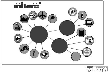
Figure 13.2 The main fields of application for contactless smart cards are public transport and change systems for telephone boxes or consumer goods (groceries, cigarettes) (reproduced by permission of Philips Electronics N.V.)
traffic associations are still operating at a huge loss, sometimes as much as 40% of turnover (Czako, 1997), which must be made up by subsidies from the community and country in question. Due to the increasing shortage of resources, long-term solutions must be sought that will cut these losses by reducing costs and increasing income. The use of contactless smart cards as electronic travel passes could make an important contribution to improving the situation (AFC = automatic fare collection). In the field of fare management in particular there is a great deal of room for improvement.
13.2.1 The starting point
The unhealthy financial situation of transport companies naturally has many different causes. However, the following factors are worth mentioning in connection with electronic travel passes:
•Transport companies incur high costs through the sale of travel passes by automatic dispensers. For example, the sale of a travel pass through an automatic dispenser in Zurich¨ costs Sfr 0.45, where the average sales price is Sfr. 2.80 (Czako, 1997). Thus, 16% of the sales price is lost from the outset by the provision of the dispenser, maintenance and repairs alone (filling with notes and coins, repairs, damage by vandalism).
•In vehicles, too, expensive electronic ticket printers or mobile devices are required. Sometimes the tickets are even sold by the driver, which causes long waiting times


 B
B