

Finkenzeller K.RFID handbook.2003
.pdf9.2 |
CONTACTLESS SMART CARDS |
261 |
|
|
|
Table 9.16 DIN/ISO 10373, ‘Identification Cards — Test methods’ |
|
|
|
|
|
Part 1 |
General |
|
|
|
|
|
|
Part |
2 |
Magnetic strip technologies |
|
Part |
3 |
Integrated circuit cards (contact smart cards) |
|
Part |
4 |
Contactless integrated circuit cards (close coupling smart cards in accordance with |
|
|
|
ISO 10536) |
|
Part |
5 |
Optical memory cards |
|
Part |
6 |
Proximity cards (contactless smart cards in accordance with ISO 14443) |
|
Part |
7 |
Vicinity cards (contactless smart cards in accordance with ISO |
|
|
|
15693) — currently still in preparation |
|
|
|
|
|
9.2.4.1 Part 4: Test procedures for close coupling smart cards
This part of the standard describes procedures for the functional testing of the physical interface of contactless close coupling smart cards in accordance with ISO 10536. The test equipment consists of defined coils and capacitive coupling areas, which facilitate the evaluation of the power and data transmission between smart card and reader.
However, due to the secondary importance of close coupling smart cards we will not investigate this procedure further at this point.
9.2.4.2Part 6: Test procedures for proximity coupling smart cards
This part of the standard describes test procedures for the functional testing of the physical interface between contactless proximity coupling smart cards and readers in accordance with ISO 14443-2. The test equipment consists of a calibration coil, a test setup for the measurement of the load modulation (PCD assembly test) and a reference card (reference PICC). This equipment is defined in the standard.
Calibration coil To facilitate the measurement of the magnetic field strength generated by a reader without complicated and expensive measuring equipment, the standard first describes the layout of a calibration coil that permits the measurement of magnetic field strengths in the frequency range of 13.56 MHz with sufficient accuracy even with a simple oscilloscope.
The calibration coil is based upon an industry-standard copper coated FR4 printed circuit board and smart card dimensions in accordance with ISO 7810 (72 mm × 42 mm × 0.76 mm). A conductor coil (i.e. a coil with one winding) with dimensions 72 mm × 42 mm is applied onto this base board using the normal procedure for the manufacture of printed circuits. The sensitivity of the calibration coil is 0.3 Vm/A. However, during the field strength measurement particular care should be taken to ensure that the calibration coil is only subjected to high-ohmic loads by the connected measuring device (sensing head of an oscilloscope), as every current flow in the calibration coil can falsify the measurement result.
If the measurement is performed using an oscilloscope, then the calibration coil is also suitable for the evaluation of the switching transitions of the ASK modulated
9.2 CONTACTLESS SMART CARDS |
263 |
Sense coil
Reference coil
Field coil
PICC (DUT)
|
|
|
|
|
|
|
|
|
|
|
|
|
|
|
|
RF drive |
|
|
|
|
Scope |
|
|
|
|
||
|
|
|
|
|
|
|
|
|
|
|
|
|
|
|
|
|
|
|
|
|
dr ds
dd
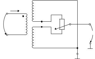
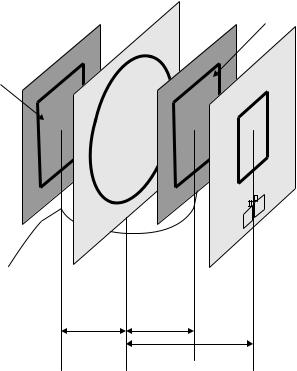
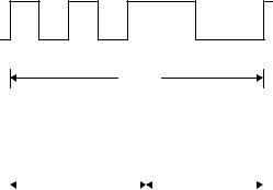
Figure 9.37 Mechanical structure of the measurement bridge, consisting of the field generator coil (field coil), the two sensor coils (sense and reference coil) and a smart card (PICC) as test object (DUT) (reproduced by permission of Philips Semiconductors, Hamburg)
the measuring bridge is disrupted in time with the switching frequency (this corresponds with the subcarrier frequency fs) as a result of the modulation resistor in the smart card being switched on and off. As a result, a subcarrier modulated HF voltage can be measured at the measurement output of the measuring bridge. This signal is sampled over several periods using a digital oscilloscope and then brought into the frequency range by a discrete Fourier transformation. The amplitudes of the two modulation sidebands fc ± fs that can be seen in the frequency range now serve as the quality criterion for the load modulator and should exceed the limit value defined in ISO 14443.
The layout of the required coils, a circuit to adapt the field coil to a 50 transmitter output stage, and the precise mechanical arrangement of the coils in the measuring arrangement are specified in the Annex to the standard, in order to facilitate its duplication in the laboratory (see Section 14.4).
Reference card As a further aid, the standard defines two different reference cards that can be used to test the power supply of a card in the field of the reader, the transient response and transient characteristics of the transmitter in the event of ASK modulation, and the demodulator in the reader’s receiver.
264 |
9 STANDARDISATION |
Umess
L |
C3 |
R1 |
|
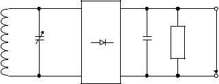
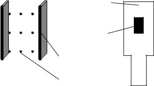
Figure 9.38 Circuit of a reference card for testing the power supply of a contactless smart card from the magnetic HF field of a reader
Power supply and modulation With the aid of a defined reference card it is possible to test whether the magnetic field generated by the reader can provide sufficient energy for the operation of a contactless smart card. The principal circuit of such a reference card is shown in Figure 9.38. This consists primarily of a transponder resonant circuit with adjustable resonant frequency, a bridge rectifier, and a set of load resistors for the simulation of the data carrier.
To carry out the test, the reference card is brought within the interrogation zone of a reader (the spatial characteristics of the reader’s interrogation field are defined by the manufacturer of this device and should be known at the start of the measurement). The output voltage Umeas of the reference card is now measured at defined resonant frequencies (fres = 13–19 MHz) and load resistances (910 , 1800 ) of the reference card. The test has been passed if the voltage within the interrogation zone does not fall below a lower limit value of 3 V.
Load modulation A second reference card can be used to provide a test procedure that makes it possible to test the adherence of the receiver in the reader to a minimum necessary sensitivity. The circuit of this test card largely corresponds with the circuit from Figure 9.38, but it has an additional load modulator.
To carry out the test, this reference card is brought into the interrogation zone of a reader, this interrogation zone being defined by the manufacturer. The reference card thus begins to transmit a continuous subcarrier signal (847 kHz in accordance with ISO 14443) by load modulation to the reader and this signal should be recognised by the reader within a defined interrogation zone. The reader under test ideally possesses a test mode for this purpose, in which the operator can be alerted to the detection of a continuous subcarrier signal.
9.2.4.3Part 7: Test procedure for vicinity coupling smart cards
This part of the standard describes test procedures for the functional testing of the physical interface between contactless smart cards and readers in accordance with ISO 15693-2. The test equipment and testing procedure for this largely correspond with the testing equipment defined in Part 6. The only differences are the different subcarrier frequencies in the layout of the reference card (simulation of load modulation) and the different field strengths in operation.

9.5 VDI 4470 — ANTI-THEFT SYSTEMS FOR GOODS |
267 |
Figure 9.41 Electronic article surveillance system in practical operation (reproduced by permission of METO EAS-System 2002, Esselte Meto, Hirschborn)
and computers, are in operation. During this test phase the products in the shop should not be fitted with security tags. During a monitoring period of one to three weeks an observer records all alarms and the conditions in which they occur (e.g. person in gates, cleaning, storm). Alarms that are caused by a security tag being carried through the gates by accident (e.g. a tag brought from another shop) are not counted.
9.5.1.2 Ascertaining the detection rate
The detection rate may be ascertained using either real or artificial products.
Real products In this case a number of representative products vulnerable to theft are selected and carried through the gateways by a test person in a number of typical hiding places — hood, breast pocket, shoe, carrier bag, etc. When selecting test products, remember that the material of a product (e.g. metal surfaces) may have a quite marked effect on the detection rate.
The detection rate of a system is calculated as the proportion of alarms triggered to the totality of tests carried out.
Artificial products This test uses a wooden rod with a tag in the form of a label attached to the middle. A test person carries this reference object through reference points in the gateway that are precisely defined by VDI 4470 at a constant speed. See Figure 9.42.
The detection rate of a system is calculated as the proportion of alarms triggered to the totality of tests carried out.
9.5.1.3 Forms in VDI 4470
In order to simplify the testing of objects and to allow tests to be performed in a consistent manner in all branches, VDI 4470 provides various forms:
•Form 1: ‘Test for False Alarms’
•Form 2: ‘Test with Real Products’

270 |
9 STANDARDISATION |
goods, but serve only as a unique identification (AI = Application Identifier) that allows the item to be looked up in a database.
Electronic Document Interchange (EDI) (defined in UN/EDIFACT) represents a further field of application of EAN.UCC systems (EAN.UCC, 2000).
The specifications currently under development facilitate the coexistence of barcode and transponder with full compatibility from the point of view of the user. This permits the flowing migration from barcodes to transponder systems, with the focus initially being placed upon applications relating to transport containers and reusable packaging (Osborne, n.d.). The requirements of such standardisation are diverse, since all parameters of such a system must be precisely specified in order to guarantee that the transponder can be implemented universally. The GTAG specification of EAN.UCC will therefore deal with three layers: the transport layer, the communication layer, and the application layer.
•The transport layer describes the physical interface between transponder and reader, i.e. transmission frequency, modulation frequency and data rate. The most important factor here is the selection of a suitable frequency so that EAN.UCC systems can be used worldwide without restrictions and can be manufactured at a low cost. Furthermore, the GTAG specification for the transport layer will flow into the future ISO 18000-6 standard (Osborne, n.d.).
•The communication layer describes the structure of the data blocks that are exchanged between transponder and reader. This also includes the definition of an anticollision procedure, plus the description of commands for the reading or writing of the transponder.
•The application layer includes the organisation and structure of the application data stored on the transponder. GTAG transponders will include at least an EAN.UCC Application Identifier (AI) (EAN.UCC, 2000). This AI was developed for data carriers with low storage capacity (barcodes). RFID transponders, however, permit additional data and provide the option of changing data in the memory, so that the GTAG specification will contain optional data fields and options.
The completion of the GTAG specification is planned for 2002 at the earliest. For this reason, only a brief overview of the technical details can be given in what follows.
9.6.2.1GTAG transport layer (physical layer)
In order to be able to fulfil the requirements of range and transmission speed imposed on GTAG, the UHF frequency range has been selected for the transponders. However, one problem in this frequency range is local differences in frequency regulations. For example, 4 W transmission power is available for RFID systems in the frequency range 910–928 MHz in America. In Europe, on the other hand, the ERO (European Radiocommunications Organisation) is currently being lobbied to allocate 2 W transmission power to the frequency range 865.6–867.6 MHz. Due to the different frequency ranges of the readers, GTAG transponders are designed so that they can be interrogated by a reader over the entire 862–928 MHz frequency range. It makes no difference in