Finkenzeller K.RFID handbook.2003
.pdf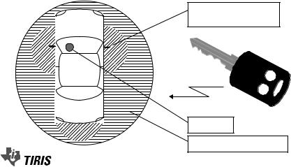
 ALARM
ALARM  OPEN
OPEN376 |
13 EXAMPLE APPLICATIONS |
Under the new conditions, only the cost of replacing the vehicle, i.e. its actual market value, is refunded in the case of loss (accident, theft, . . .). Furthermore, if the loss is due to theft an excess is deducted from the payment, which may be waived if the vehicle is fitted with an approved anti-theft device (Wolff, 1994). The vehicle owner’s own interest in having an effective anti-theft device was significantly increased by the new insurance conditions.
The effectiveness of electronic immobilisation has been clearly demonstrated by the decreasing trend in vehicle thefts in Germany. In 1994 there had already been a slight fall of about 2000 to 142 113, compared to the record figure from 1993. Two years later — 1996 — 110 764 thefts were reported. This represents a fall of 22% in just 2 years.
Another factor is that since 1995 electronic immobilisers have been fitted to all new cars — with a few exceptions — in the factory as standard. If we consider vehicles secured in this manner alone, then we can expect a reduction in the theft rate by a factor of 40(!).
In this connection it is interesting to examine investigations by insurance companies into vehicle thefts where electronic immobilisers were fitted (Anselm, 1995, 1996; Caspers, 1997).
Of 147 stolen vehicles in 1996, 70% of thefts were performed using the original key, which the thief had obtained by breaking into homes, garages and workshops, or by stealing from offices, bags and changing rooms or by the fraudulent renting and misappropriation of rental or demonstration cars. In the remaining 30% of cases, the vehicles either disappeared under circumstances that indicated the cooperation of the owner (without this being proved in individual cases), or vehicles were loaded onto lorries and transported away by professionals.
There has not been one case since 1995 where the electronic immobiliser has been ‘cracked’ or beaten by a thief.
13.7.3 Predictions
The next generation of immobilisers will also incorporate a passive, cryptologically secured access system. In this system, a reader will be fitted in each of the vehicle’s doors. Sequential systems (TIRIS ) will be able to achieve a remote range, in which the transponder is supplied by a battery, so that the vehicle’s central locking system can be operated from a greater distance away. This is similar in its function to the combination of an immobiliser and central locking remote control on a single transponder.
13.8Container Identification
13.8.1 Gas bottles and chemical containers
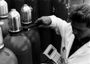
Gas and chemicals are transported in high quality rented containers. Selecting the wrong bottle during refilling or use could have fatal consequences. In addition to product specific sealing systems, a clear identification system can help to prevent such errors. A machine readable identification system gives additional protection (Braunkohle, 1997).
378 |
13 EXAMPLE APPLICATIONS |
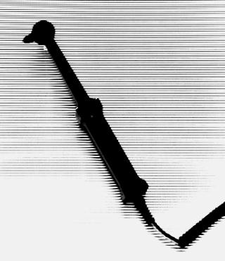
Figure 13.39 Portable antenna for reading inductively coupled transponders mounted on gas bottles or other containers (reproduced by permission of SCEMTEC Transponder Technology GmbH, Reichshof-Wehnrath)
containers dirty (Braunkohle, 1997). For gas, where there is not much potential for product differentiation between manufacturers, the associated cost savings can convey an important competitive advantage (Buhrlen,¨ 1995).
In total, over eight million gas bottles in Germany alone are waiting to be fitted with transponders. For Europe, this figure is approximately 30 million. In addition to gas bottles, transponders are also used for rental containers, beer kegs and boxes and transportation containers for the delivery industry.
13.8.2 Waste disposal
Because of increasingly rigorous environmental legislation, the cost of waste disposal is increasing all the time. Costs associated with creating new waste disposal sites and maintaining existing sites are being passed on to individual households and industrial companies. Automatic measurement of the amount of waste produced helps to distribute the costs fairly. For this reason, more and more cities are using RFID systems to optimise communal waste disposal, and are thus putting the conditions in place for replacing the flat rate charge for waste disposal with a charge based upon the quantity
13.9 SPORTING EVENTS |
379 |
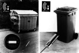
Figure 13.40 Left, dustbin transponder for fitting onto metal surfaces; right, reader antenna for installation in the dustcart. A plastic dustbin fitted with a transponder is shown in the background (reproduced by permission of Deister Electronic, Barsinghausen)
of waste produced. The waste disposal companies will only charge for the amount that has actually been removed.
To achieve this goal, a transponder is fitted to the dustbin and automatic reader systems are installed in rubbish collection vehicles (Figure 13.40). As soon as the dustbin is placed on the vehicle’s emptying device its transponder is read. In addition, either the weight or the volume of rubbish is calculated, depending upon the preference of the community. A counter, to show how often the bin has been emptied in the year, is also feasible (EURO-ID, n.d.).
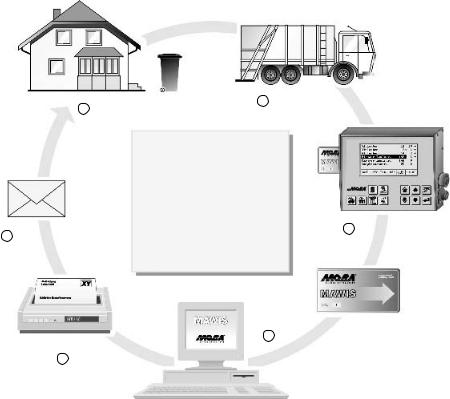
The identifier read by the transponder is stored in a smart card in the vehicle’s on-board computer together with the data collected. At the end of a round the driver passes the card to the operations centre so that the collected data can be processed. Individual households no longer pay a monthly flat rate, but each receive an individual bill (Prawitz, 1996) (Figure 13.41).
In Germany RFID systems are already in use in various cities, including Bremen, Cologne and Dresden, and in numerous communities.
13.9Sporting Events
In large-scale sporting events such as major marathons, the runners who start at the back of the field are always at a disadvantage, because their times are calculated from the moment the race is started. For many runners it takes several minutes before they actually cross the starting line. In very large events with 10 000 participants or more, it might be 5 minutes before the last runners have crossed the starting line. Without individual timing, the runners in the back rows are therefore at a severe disadvantage.
To rectify this injustice, all runners carry a transponder with them. The system is based upon the idea that each runner places his feet repeatedly on the ground and thus comes very close to a ground antenna. In experimental events it was found that using a ingenious arrangement of multiple antennas in an array and a chip in the shoe over 1000 runners can be registered up to eight times in a minute with a start width of just 4 m (ChampionChip, n.d.).
13.10 INDUSTRIAL AUTOMATION |
381 |
|||||
|
|
|
|
|
|
|
|
|
|
|
|
|
|
|
|
|
|
|
|
|
|
|
|
|
|
|
|
|
|
|
|
|
|
|
|
|
|
|
|
|
|
Glass transponder
Plastic holder
Figure 13.42 The transponder consists of a glass transponder, which is injected into a plastic housing that is shaped according to its function. The diagram shows the partially cut away plastic housing
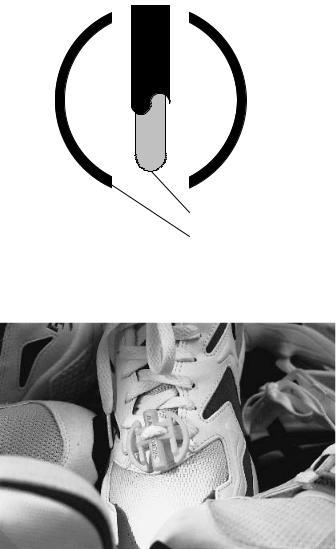
Figure 13.43 The ChampionChip transponder is fastened to the runner’s shoe with the shoelace (reproduced by permission of ChampionChip BV, NL-Nijmegen)
13.10Industrial Automation
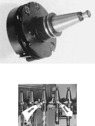
13.10.1 Tool identification
As well as its metal cutting tool industry, Germany’s woodworking industry also plays a dominant role in the world market. The modern woodworking and furniture manufacturing industry is dominated by CNC technology because this enables manufacturers to manufacture at a low cost and remain competitive.
382 |
|
|
|
|
|
|
|
|
|
|
|
|
|
|
13 EXAMPLE APPLICATIONS |
|
|
Backup system |
|
|
|
|
Main system |
||||||||||
|
|
|
|
|
|
|
|
|
|
|
|
|
|
|
|
|
|
|
|
|
|
|
|
|
|
|
|
|
|
|
|
|
|
|
|
|
|
|
|
|
|
|
|
|
|
|
|
Start- |
|
|
|
|
|
|
|
|
|
|
|
|
|
|
|
|
finish |
line |
|
|
|
|
|
|
|
|
|
|
|
|
|
|
|
|
|
|
|
|
|
|
|
|
|
|
|
|
|
|
|
|
|
|
|
|
|
|
|
8 |
m |
|
|
|
|
|
|
|
|
|
Race direction |
|
|
|
|
|
|
|
|
|
|
|
|
|
|
||||
|
|
|
|
|
|
|
|
|
|
|
|
|
|
|
|
|
|
|
|
|
|
|
|
|
|
|
|
|
|
|
|
|
|
|
|
|
|
|
|
|
|
|
|
|
|
|
|
|
|
|
|
|
|
|
|
|
|
|
|
|
|
|
|
|
|
|
|
|
|
|
|
|
|
|
|
|
|
|
|
|
|
|
|
|
|
|
|
|
|
|
|
|
|
|
|
|
|
|
|
|
|
Control unit
Reader
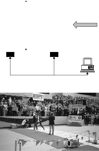
Figure 13.44 A control station consists of a main system and a reserve system. The systems are made up of arrays of antennas in mats
Figure 13.45 Runners passing the control station at the end of the 101st Boston Marathon. In the foreground we can see the mats containing the readers. The times can be displayed on a screen immediately (reproduced by permission of ChampionChip, NL-Nijmegen)
CNC machines equipped with tool holders and automatic tool changers fulfil tasks that are increasingly associated with small batch production. This increases the proportion of manufacturing costs incurred by retooling and tool-change times.
Another consideration is the fact that a CNC woodworking machine differs from a metalworking machine because of its higher rotation and path speeds. Rotation speeds