

Finkenzeller K.RFID handbook.2003
.pdf384 |
|
13 EXAMPLE APPLICATIONS |
||
|
Production |
Measure |
|
|
|
use in CNC |
|
|
|
|
tool |
|
|
|
|
machine |
|
|
|
|
|
|
|
|
Read |
|
|
|
|
operation |
Tool store |
Sharpen |
||
in tool |
|
tool |
||
|
|
|||
changer |
|
|
|
|
|
Insert |
Measure and |
|
|
|
tools in random |
|
|
|
|
recode tool |
|
|
|
|
order |
|
|
|
|
|
|
|
|
|
Production cycle |
Service cycle |
|
|
Figure 13.48 Representation of the tool cycle when using transponder coded CNC tools |
||||
|
Table 13.4 Example of a data record for a tool transponder |
|
||
|
|
|
|
|
|
Customer |
Furniture Production |
|
|
|
|
Plant XY |
|
|
|
LEITZ ID no. |
130004711 D25x60 |
|
|
|
Manufacturing ref. |
Y21 |
|
|
|
Place of manufacture |
UHE |
|
|
|
Rotation direction |
3 |
|
|
|
Max. rotation speed |
24 000 |
|
|
|
Min. rotation speed |
18 000 |
|
|
|
Ideal rotation speed |
20 000 |
|
|
|
Radius correction |
25 011 |
|
|
|
Longitudinal correction |
145 893 |
|
|
|
Greatest radius |
25 500 |
|
|
|
Greatest length |
145 893 |
|
|
|
Maximum travel |
3000 |
|
|
|
Current travel |
875 |
|
|
|
Tool number |
14 |
|
|
|
Tool type |
1 |
|
|
|
Number of sharpenings |
2 |
|
|
|
Angle of clearance |
20 |
|
|
|
Cutting rake |
15 |
|
|
|
Free text |
Finishing cutter HM Z = 3 |
|
|
Inductively coupled transponders operating in the frequency range <135 kHz are used. The transponder coil is mounted on a ferrite core to shield it from the metal surface (see also Sections 4.1.12.3 and 2.2). The transponder must have a minimum of 256 bytes of memory, which is written with an ASCII string containing the required tool data. An example of a data record is illustrated in Table 13.4 (from Leitz, n.d.).
Modern transponder coded CNC tools can be incorporated into a cost saving production and service cycle. The service cycle is incorporated, smoothly and simply, into the production cycle as follows.
13.10 INDUSTRIAL AUTOMATION |
385 |
The worn tool is first examined and measured in detail to determine its condition. The tool is then serviced, sharpened and balanced on the basis of this data. After every maintenance sequence the tool length and radius is updated and written to the transponder, so that correctly dimensioned workpieces are produced by both new and sharpened tools without intervention by the operator.
13.10.2 Industrial production
Production processes underwent a process of continuous rationalisation during the development of industrial mass production. This soon led to production line assembly (‘conveyor belt production’), with the same stage of production being performed at a certain position on the assembly line time after time. For the present, a production process of this type is only able to produce objects that are identical in function and appearance. However, the days are numbered for machines that produce large quantities of a single product with no variants.
If different variants of a product are to be produced at the same time on an assembly line in an automated procedure, the object must be identified and its status clearly recognised at every work station, so that the correct processes can be performed. Originally, this was achieved by objects being accompanied by process cards, which gave the operating personnel all the information required at a particular work station — the desired paint colour, for example. This was first achieved in electronic form using coding pegs affixed to the revolving palettes so that palette numbers could be read by the electronic control system. The position of these coding pegs could be sensed by inductive proximity switches (Weisshaupt and Gubler, 1992). This procedure has recently been improved by the use of barcode labels, which can simply be stuck onto the individual objects.
RFID technology now provides an additional option — data carriers that can not only be read, but also written. Now, in addition to recording the identity of an object, it is also possible to document its current status (e.g. processing level, quality data) and the past and future (desired end state) of the object.
Using modern identification techniques, production systems can now be realised which can produce variants of a product, or even different products, down to a batch size of one (Weisshaupt and Gubler, 1992). The automotive industry is a good example: since vehicles are predominantly produced to order and it is rare for two identical vehicles to be ordered, automatic material flow tracking is crucial to smooth operation. A vehicle must be clearly identified at the individual manufacturing stages to avoid, for example, an unwanted air conditioning system from being fitted, or the wrong paint colour being applied during painting (Homburg, 1996).
There are two possible methods of controlling a system based upon object data: centralised and decentralised control.
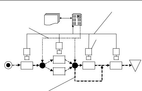
Centralised control In this approach, material flow and object status are continuously monitored during the process and are stored in a database on a central computer (Figure 13.49). This builds up an image of the current process data and system status in the process control system of the central computer. It makes no difference whether the status of objects in the process is determined using barcodes, radio, optical character recognition, RFID or any other type of information coding and transmission.
386 |
|
|
|
13 EXAMPLE APPLICATIONS |
|
Database |
Central computer |
Object status and |
|
|
|
|
|
identification |
Control commands |
|
|
|
|
|
|
|
|
Reader |
Goods inwards |
Paint 1 |
|
|
Stores |
|
|
|
|
|
Drill |
? |
? |
Addition |
Gluing |
|
Paint 2 |
|
|
|
Object and material flow
Figure 13.49 The object and data flow in a central control system is performed using completely separate routes. The central computer has a powerful database in which all process data is stored
The monitoring of the process must be completely infallible, otherwise there is a danger that an object will become out of control. The restarting of the system after a fault or the crashing of the control software can be a particularly critical moment.
Centralised control systems based upon a powerful central database are particularly common when it is necessary to access the information from different locations simultaneously, when a transparent image of process data must be available continuously for other purposes, or if important data needs to be stored permanently (Homburg, 1996). Apart from production, typical applications include stores technology, logistics or the collection of operating data.
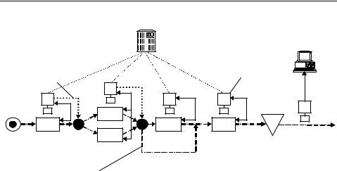
Decentralised control The use of readable and writable data carriers opens up the possibility of controlling a system locally, i.e. completely independently of the central process computer. Each object carries a complete data record with it that contains information about its identity, its current status, its history and its future — material and data flow are thus interlinked (Figure 13.50). For this to be successful, it must be possible not only to read the relevant data from the object at each processing station, but also to change and update this information. Of all known identification technologies, this can only be achieved with the necessary reliability using writable RFID transponders.
The option of changing the object data in the transponder at each processing station means that it is possible to create an information flow between the individual processing stations, which takes the pressure off the control system. Production and processing operations are becoming faster all the time, so the fact that information can be carried with the object and is available in the right place can become a decisive factor in speeding processes up. Due to possible overheads associated with accessing a remote
13.10 INDUSTRIAL AUTOMATION |
387 |
|
Central computer |
|
|
Monitoring the |
Object history |
|
process status |
||
QA data |
||
|
Control commands |
|
|
|
Reader |
|
|
|
|
|
Goods |
|
|
|
Stores |
inwards |
|
Paint |
|
|
|
|
|
|
|
Drilling |
? |
? |
Addition |
Gluing |
|
|
Paint 2 |
|
|
Object, material and data flow
Figure 13.50 In a decentralised system the data is carried along with the objects
database, readers in systems that operate at a rate of seconds are becoming increasingly unable to keep pace with the process, for example in the setting of points or the initiation of the correct processing operation (Homburg, 1996).
13.10.2.1Benefits from the use of RFID systems
•Quality control: In modern production lines the quality of products is tested at test points located at a number of stations. When the product is inspected at the end of the production process, it must be possible to unambiguously attribute the quality data gathered earlier to the correct object. With writable transponders that travel with the product this is easy to achieve because all the quality data obtained during the production process is carried with the object.
•System security: Shifting object data from the central computer to the object significantly increases system security. Even after software crashes or failures of the central computer, the relationship between an object and its current data can be established anywhere and at any time. If necessary, objects can also be withdrawn from the production process without losing the data. If the object is subsequently put back into the process, work can continue without problems or faults occurring (Weisshaupt and Gubler, 1992).
•Data security: Protecting the data stored in the transponder using a checksum procedure (e.g. CRC, see Section 7.1) ensures the complete security of the data that has been read. Read errors are recognised as such and the data ignored.
•Flexibility: The use of writable transponders facilitates much more flexible control of the manufacturing process. For example, the setup data for universally programmable robots and production machines can be written to the transponder carried with the object during the preparatory stage and is available immediately where it is needed. Using this technique, products can be manufactured right down

388 |
13 EXAMPLE APPLICATIONS |
to a batch size of one, without having to set up a complex communication with the central computer for each object.
•Harsh environmental conditions: RFID systems are completely insensitive to dust, moisture, oils, coolants, cuttings, gases, high temperatures and similar problems that can occur in a manufacturing environment. Glass and plastic transponders usually comply with protection type IP67; that is, they are totally dustproof and waterproof.
Even particularly dusty or dirty environmental conditions, which would make the use of barcode readers impossible due to the rapid blocking of scanner optics, pose no problems for RFID systems.
13.10.2.2The selection of a suitable RFID system
When selecting a suitable RFID system for use in the production process, the characteristics of the different memory technologies should be considered (see Table 13.5; see also Section 10.3).
EEPROM Data stored in an EEPROM is retained for several years without a power supply. The energy required for writing to or reading from a transponder using EEPROM technology is transmitted by inductive coupling. Since the transponders do not require a battery they may be very small. The guaranteed number of write access operations to a memory address is typically around 100 000 cycles, which is greater than the lifetime of the transponder. However, an innovative type of EEPROM technology is now available on the market which can be reprogrammed more than 106 times. This
Table 13.5 Comparison between the two memory technologies for transponders
|
EEPROM/FRAM |
SRAM |
|
|
|
Memory size |
16 byte–32 Kbyte |
1–512 Kbytes |
Data transmission |
Inductive coupling |
Inductive coupling, |
|
|
backscatter |
Power supply |
Inductive coupling |
Battery |
Typical number of |
EEPROM: 100 000–1 000 000 |
Unlimited |
write cycles |
FRAM: 1010 |
|
Typical temperature |
−20 ◦C–120 ◦C |
0 ◦C–60 ◦C |
range |
|
|
Applications |
Applications with a limited |
Applications with any |
|
number of reprogramming |
number of reprogramming |
|
operations (EEPROM) |
operations, e.g. in assembly |
|
|
systems |
|
Applications with expanded |
Use in the ‘normal’ industrial |
|
temperature range |
temperature range |
|
— |
Need for higher memory size |
|
|
with short transaction time |
|
— |
Large transponder range |
|
|
required (or low positional |
|
|
accuracy) |
|
|
|

390 13 EXAMPLE APPLICATIONS
soon as the body enters the interrogation zone of a reader the read process is initiated by an inductive proximity switch. The required data is read from, or if necessary written to, the transponder. The transponders are equipped with a battery designed for a lifetime of 8 years. They have a memory size of 32 Kbytes, and the range of up to 4 m is sufficient in all stages of assembly (Pepperl & Fuchs, 1998, n.d.a).
In Mercedes Benz’s Tuscaloosa factory in the USA, inductively coupled transponders (125 kHz, read-only system) are used for the identification of skids for vehicle bodies. After the skid has travelled through the painting line several times it must be cleaned. This selection process can be performed without incurring additional costs by data capture using transponders (schenk, 1997).
In the production of its 1E generation, vehicle manufacturer General Motors produces 26 different engine models under one roof at its Flint factory (Michigan, USA). The product range incorporates a multitude of engine types, which includes 1997 to 1998 models, 5.0 to 5.7 litre engines, engines for automatic or shift transmission, engines for export, engines designed to run on environmental fuel and petrol, and engines for cars and lorries. Fitting the product carriers with transponders (13.56 MHz, 8 Kbyte memory) makes it possible to track and identify all engine models throughout the production process. Using RFID it is possible to trace any engine in the factory within seconds. Around 50 readers are installed in the production area for this purpose (Escort, 1998a).
The John Deere Company in Waterloo (Iowa, USA), the worldwide market leader in the production of agricultural machinery, employs an inductively coupled RFID system in the manufacture of tractors. The tractor bodies are equipped with special transponders that can withstand temperatures of up to 225 ◦C, and can even communicate with a reader at these temperatures, which means that they can be used in the painting ovens (Escort, 1998b). The data carriers (13.56 MHz, 8 Kbyte memory) can be easily fitted to the rear axle of the tractor chassis. Because most tractors are manufactured to order, the use of modern identification technology allows tractors to be adapted to individual customer requirements.
The use of RFID systems in the meat processing industry is another interesting example. Barcode systems cannot be used due to the high temperatures of above 100 ◦C during canning and the long cooling periods. The company J. M. Schneider Meats, one of the largest meat processing companies in Canada with 15 factories, therefore uses an inductively coupled RFID system in the processing sequence for product identification and tracking. At the beginning of the process the meat is stacked onto mobile shelves. The meat is conveyed into the chill room via the smoking chambers on these shelves and in the last stage of processing it is heated to above 100 ◦C for conservation. It is vital that the company always knows precisely where the individual shelves are and which process they are currently undergoing. Transponders are therefore attached to the individual shelves (13.56 MHz) and significant data, such as the location of the shelves, meat type and weight data, is written to the transponder. The delivery time of the meat, which depends upon its use-by date, can also be consistently tracked by means of the RFID system (Escort, 1998c).
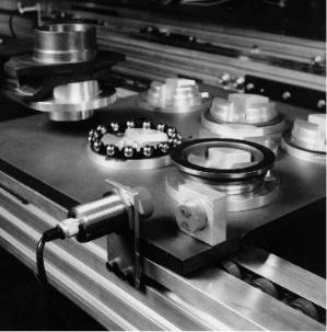
A further application that should clarify how RFID systems can help to increase the quality of a product by tolerance selection (Pepperl & Fuchs, n.d.b) is illustrated in Figure 13.52. This application involves the assembly of a precision clutch release stop. The system consists of a pallet rotary system, two robots and a manual work
13.10 INDUSTRIAL AUTOMATION |
391 |
Figure 13.52 Individual components of a clutch release stop on a revolving pallet. Transponder and reader antenna are visible in the lower part of the photo (reproduced by permission of Pepperl & Fuchs, Mannheim)
station. All the pallets are equipped with transponders. The individual components that make up the stop are measured by one of the robots and these measurements are used to assemble components so that the play in the finished stop is minimised. This allocation of individual components to each other is written as data to the transponder and thus carried along with the individual components. The second robot is an assembly robot which assembles the individual components into a stop. At this point the data is read from the transponder, so that the robot can always assemble the correct individual components.
The use of RFID systems can also bring benefits in storekeeping and order processing. One of the leading pharmaceutical companies, Sanacorp in Munich, has an electronically controlled stock keeping and order processing system, which allows products to be automatically collected in accordance with the delivery note. More than 6000 consignment containers (plastic containers) pass through the stores every day and need to be identified at individual loading points. In the old system using barcode labels or reflective code labels up to 100 errors occurred daily, meaning that the falsely identified consignment containers passed through all of the loading points on the way to the goods outwards, thus delaying the entire consignment. To guarantee the infallible recognition of the consignment containers these were fitted with transponders (134 kHz, SEQ), which were welded to the base of the plastic trough. The reader antennas are located under the conveyor belts at the relevant stations. As soon as a consignment container rolls into the interrogation zone of a reader the transponder is read and the stored data is transferred to the stock-control computer. The central computer is informed of where each consignment container is located, whether delays
13.11 MEDICAL APPLICATIONS |
393 |
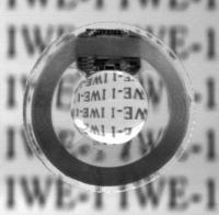
Figure 13.54 Cast transponder unit deformed by a pair of tweezers (reproduced by permission of IWE1, RWTH Aachen, D-52074 Aachen)
|
External telemetric |
|||
External coil |
components |
Spectacles Cable to hand-held-unit |
||
|
|
|
|
|
|
|
|
|
|
|
|
|
|
|
Pressure sensor,
internal telemetric components
 Eye
Eye
Artificial interocular lens
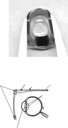
Figure 13.55 An implanted transponder with a pressure sensor, and an antenna coil integrated into the frame of a pair of glasses make up the system for the continuous measurement of interocular pressure (reproduced by permission of IWE1, RWTH Aachen, D-52074 Aachen)
and is thus foldable, which makes the implanting of the transponder much easier (see Figure 13.54). The pressure sensor is micromechanically integrated into he transponder chip and has a sensitivity of 1.3 mbar, which roughly corresponds with the precision of current tonometer measurements (Ullerich 2001).
So that the transponder can be read continuously, the reader’s antenna is integrated into the frame of a pair of glasses. The control of the coil and the storage of the measured data takes place with the aid of the reader, which is connected to the glasses via a cable (Figure 13.55).