

Finkenzeller K.RFID handbook.2003
.pdf364 13 EXAMPLE APPLICATIONS
The reader’s signal is not modulated (read-only transponder). The specified maximum reader distance is 13 m.
ISO 10374 specifies the following information that can be stored in the transponder:
•owner’s code, serial number and test digit;
•container length, height and width;
•container type, i.e. suitcase container, tank container, open top container and others;
•laden and tare weight.
A battery provides the power supply to the electronic data carrier in the transponder (active transponder). The lifetime of the battery corresponds with the lifetime of the container itself, i.e. around 10 to 15 years.
The same technology is used in the identification of goods wagons in North American and European railway transport. A European standard is in preparation for the automatic identification of European interchangeable containers (Siedelmann, 1997).
13.6Animal Identification
13.6.1 Stock keeping
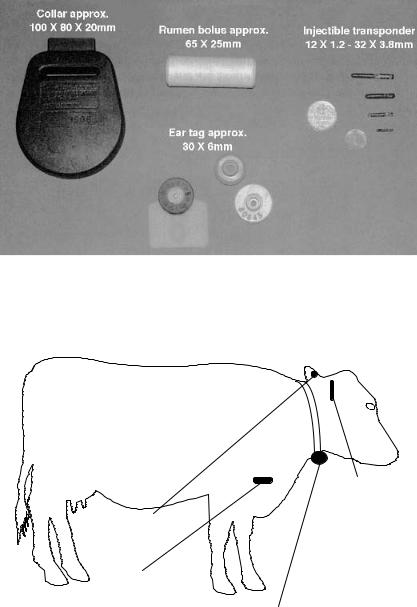
Electronic identification systems have been used in stock keeping for almost 20 years (Kern and Wendl, 1997) and are now state of the art in Europe. In addition to internal applications for automatic feeding and calculating productivity, these systems can also be used in inter-company identification, for the control of epidemics and quality assurance and for tracing the origin of animals. The required unified data transmission and coding procedures are provided by the 1996 ISO standards 11784 and 11785 (see Section 9.1). The specified frequency is 134.2 kHz, and FDX and SEQ transponders can both be used. A size comparison of the various transponders is given in Figure 13.22.
There are four basic procedures for attaching the transponder to the animal: collar transponders, ear tag transponders, injectible transponders and the so-called bolus (Figure 13.23). Cross-sections of different types of transponders are shown in Figure 13.24.
Collar transponders can be easily transferred from one animal to another. This permits the use of this system within a company. Possible applications are automatic feeding in a feeding stall and measuring milk output.
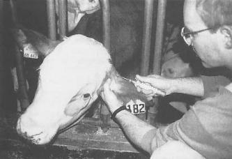
Ear tags incorporating an RFID transponder compete with the much cheaper barcode ear tags. However, the latter are not suitable for total automation, because barcode ear tags must be passed a few centimetres from a hand reader to identify the animal. RFID ear tags, on the other hand, can be read at a distance of up to 1 m.
Injectible transponders were first used around 10 years ago. In this system, the transponder is placed under the animal’s skin using a special tool. A fixed connection is thereby made between the animal’s body and the transponder, which can only be removed by an operation. This allows the use of implants in inter-company applications, such as the verification of origin and the control of epidemics.
13.6 ANIMAL IDENTIFICATION |
365 |
Figure 13.22 Size comparison of different variants of electronic animal identification transponders: collar transponder, rumen bolus, ear tags with transponder, injectible transponder (reproduced by permission of Dr Michael Klindtworth, Bayrische Landesanstalt fur¨ Landtechnik, Freising)
Injectible transponder
Ear tag
Bolus
Collar transponder
Figure 13.23 The options for attaching the transponder to a cow
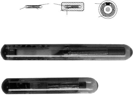
The implant is in the form of a glass transponder of 10, 20 or 30 mm in length (Figure 13.25). The transponder is supplied in a sterile package or with a dose of disinfectant. The dimensions of the glass transponder are amazingly small, considering that they contain the chip and a coil wound around a ferrite rod. A typical format is 23.1 mm × 3.85 mm (Texas Instruments, 1996).
366 |
|
|
13 EXAMPLE APPLICATIONS |
Injectible transponder |
Bolus |
Ear tag |
|
|
IC |
|
IC |
Glass shell |
Ferrite antenna |
Ceramics |
Loop |
|
|
||
|
|
|
antenna |
Figure 13.24 Cross-sections of various transponder designs for animal identification (reproduced by permission of Dr Georg Wendl, Landtechnischer Verein in Bayern e.V., Freising)
Figure 13.25 Enlargement of different types of glass transponder (reproduced by permission of Texas Instruments)
Various instruments and injection needles are available for performing the injection:
•‘Single-shot’ devices use closed hollow needles (‘O’ shape), which are loaded individually. Single use needles containing transponders in a sterile package are also available. The hollow needles are sharpened at the tip, so that the skin of the animal is ripped open when the needle is inserted. The blunt upper part of the needle tip presses the cut flap of skin to one side so that the insertion point is covered up again when the needle has been removed, allowing the wound to heal quickly (Kern, 1994).
•The ‘Multi-shot’ device has a magazine for several transponders, thus dispensing with the need to load the device. Open-ended hollow needles (‘U’ shaped) are used, as these are easier to clean, disinfect and check than closed hollow needles and can therefore be used several times.
The injection does not hurt the animal and can be carried out by practised laymen. However, attention should be given to hygiene to ensure that the wound heals safely.
An injected transponder represents a foreign body in the animal’s tissues. This can lead to problems in the locational stability of the transponder within the animal’s body, and may therefore cause problems when reading the transponder. From our experience of war injuries we know that shrapnel can often wander several decimetres through the body during a person’s lifetime. An injected transponder can also ‘wander’ around. To solve this problem, the Bayerischen Landesanstalt fur¨ Landtechnik in Weihenstephan, a
368 |
13 EXAMPLE APPLICATIONS |
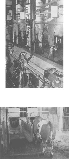
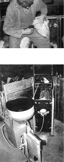
Figure 13.27 Automatic identification and calculation of milk production in the milking booth (reproduced by permission of Dr Georg Wendl, Landtechnischer Verein in Bayern e.V., Freising)
Figure 13.28 Output related dosing of concentrated feed at an automatic feed booth for milk cows. In the illustration the cow is identified by the transponder at its neck (reproduced by permission of Dr Georg Wendl, Landtechnischer Verein in Bayern e.V., Freising)
distance from their home. Pigeons are judged by the time they take to return home from the point where they were released. One problem is the reliable recording (confirmation) of arrival times, because in the past the breeders themselves recorded the times using a mechanical confirmation clock.
370 |
13 EXAMPLE APPLICATIONS |
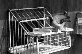
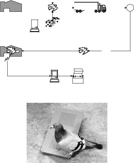
Figure 13.31 Pigeon upon arrival at its own pigeonry. Upon the pigeon’s entry, the transponder in the ring is read (reproduced by permission of Legic Identsystems, CH-Wetzikon)
To solve the problem of timing, the pigeons are fitted with rings that incorporate a read-only transponder based upon a glass transponder. As the pigeons are loaded onto the transporter for transport to the release site, the serial numbers of the transponders are read to register the animals for participation in the race. Upon the pigeon’s arrival at its home pigeonry a reader installed in the pigeonhole records the serial number and stores it, together with the precise arrival time, in a portable control unit. Judging takes place by the reading of the devices at the operating point (Figure 13.31).
However, the ingenuity of some of the breeders was greatly underestimated when this system was first introduced. It was not long before some breeders were not only able to read the transponder codes from the pigeon ring, but could also fool the reader using a simulation device in the home pigeonry. The technology involved was fairly simple — all that was required was an extremely simple read-only transponder, whose ‘serial number’ could be altered using external DIP switches. Thus, some breeders were able to significantly accelerate the ‘flight speeds’ of their champions.
An effective measure to protect against such attempts at fraud is the incorporation of an additional writable EEPROM memory into the transponder. The memory size is just 1 byte to keep the chip size and cost of circuitry low (Figure 13.32). Before the start, a previously determined random number, for which there are 28 = 256 possibilities, is written to this byte in the transponder at the headquarters. It is crucial that the breeder does not have access to his bird while it is being transported to the release site after the transponder has been programmed. This prevents the random number from being read. When the pigeon reaches its home pigeonry, its arrival is confirmed electronically. The time, together with the transponder code and the secret random number are stored. When the records are evaluated at the headquarters, the random number read upon arrival is compared with the number programmed at the start. The measured times are only validated if the two figures are identical, otherwise it is assumed that an attempted fraud has taken place.
The procedure described is clearly adequate to successfully prevent attempted fraud. With 256 possibilities for the random number the probability that this will be guessed correctly in a single attempt is only 0.4%.
In order to keep the weight and dimensions of the pigeon transponder low, glass transponders are used in this application, which are cast into a plastic ring. These plastic

372 13 EXAMPLE APPLICATIONS
remote control devices with a range of 5–20 m had already been available on the market for years. These are small infrared or RF transmitters operating on the UHF frequency 433.92 MHz, which are primarily used to control the central locking system and an integral alarm. An (electronic) immobiliser may also be coupled to the remote control function. In this type of anti-theft device, however, the mechanical lock can still be used to gain access to the vehicle — in case the remote control device fails to work due to the failure of the battery in the transmitter. This is the greatest weakness of this type of system, as the system cannot check whether the mechanical key is genuine. Vehicles secured in this manner can therefore be opened with a suitable tool (e.g. picklock) and started up by an unauthorised person.
Since the middle of the 1990s, transponder technology has provided a solution that can be used to check the authenticity, i.e. the genuineness, of the key. This solution has proved ideal for the realisation of the electronic immobilisation function via the ignition lock. Today, transponder technology is usually combined with the above-mentioned remote control system: the remote control operates the vehicle’s central locking and alarm system, while transponder technology performs the immobilisation function.
13.7.1 The functionality of an immobilisation system
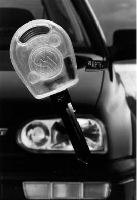
In an electronic immobilisation system a mechanical ignition key is combined with a transponder. The miniature transponder with a ferrite antenna is incorporated directly into the top of the key (see Figure 13.34). The antenna is integrated into the ignition lock (Figure 13.35).
The reader antenna is integrated into the ignition lock in such a manner that when the ignition key is inserted, the (inductive) coupling between reader antenna and transponder coil is optimised. The transponder is supplied with energy via the inductive coupling and is therefore totally maintenance free. Electronic immobilisers typically operate at a transmission frequency in the LF range 100–135 kHz. ASK modulation is the preferred modulation procedure for the data transfer to the transponder, because it allows reader and transponder to be manufactured very cheaply (Doerfler, 1994). Load modulation is the only procedure used for data transmission from the transponder to the reader.
When the ignition key is turned in the ignition lock to start the vehicle, the reader is activated and data is exchanged with the transponder in the ignition key. Three procedures are employed to check the authenticity of the key:
•Checking of an individual serial number. In almost all transponder systems the transponder has a simple individual serial number (unique number). If the normal
number of binary positions is used, significantly more different codes are available than worldwide car production (232 = 4.3 billion, 248 = 2.8 × 10¹⁴). Very simple systems (first generation immobilisation) read the transponder’s serial number and compare this with a reference number stored in the reader. If the two numbers are identical the motor electronics are released. The problem here is the fact that the transponder serial number is not protected against unauthorised reading and, in theory, this serial number could be read by an attacker and copied to a special transponder with a writable serial number.
•Rolling code procedure. Every time the key is operated a new number is written to the key transponder’s memory. This number is generated by a pseudo-random
13.7 ELECTRONIC IMMOBILISATION |
373 |
Figure 13.34 Ignition key with integral transponder (reproduced by permission of Philips Electronics N.V.)
generator in the vehicle reader. It is therefore impossible to duplicate the transponder if this system is used. If several keys are used with one vehicle then each key runs through its own pseudo-random sequence.
•Cryptographic procedures (authentication) with fixed keys. The use of cryptographic procedures offers much greater security (second generation immobilisation). In the authentication sequence (challenge response) knowledge of a secret (binary) key is checked, without this key being transmitted (see Chapter 8). In vehicle applications, however, unilateral authentication of the key transponder by the reader in the ignition lock is sufficient.
The RFID reader now communicates with the vehicle’s motor electronics, although this communication is protected by cryptographic procedures. The motor electronics control all important vehicle functions, in particular the ignition system and fuel system. Simply short circuiting or disconnecting certain cables and wires is no longer sufficient to circumvent an electronic immobilisation system (Figure 13.36). Even attempting to fool the motor electronics by inserting another ignition key of the same type into the ignition lock is bound to fail because of the authentication procedure between reader and motor electronics. Only the vehicle’s own key has the correct (binary) key to successfully complete the authentication sequence with the motor electronics.