

Finkenzeller K.RFID handbook.2003
.pdf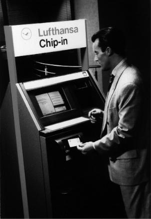
13.3 TICKETING |
355 |
Figure 13.13 Passenger checking in using the contactless Miles & More Frequent Flyer Card (reproduced by permission of Lufthansa)
number. With the new cards, the booking may be performed up to one hour before departure. An electronic ticket is created that combines personal data and the flight data, and this is saved in the Lufthansa computer. To check in at the airport (at the last minute) the smart card owner only has to present his contactless smart card briefly at the Chip-In-Terminal (Figure 13.13). Normally, he can do this without even removing the card from his briefcase. The system verifies the booking, and the flight data appear on the screen. At this point the passenger is given the option of either confirming the suggested flight including seat reservation or selecting an alternative flight on the touch screen monitor. The passenger receives a printed receipt specifying his seat number and boarding gate, plus other details. This procedure allows the passenger to check in with his hand luggage in less than 10 seconds, which helps to prevent queues at the terminal. When he arrives at the boarding gate he merely presents his ChipCard once again and can then board.
The new ChipCard solution benefits both passengers and Lufthansa and AirPlus. The passengers are overjoyed about the time saving on the ground, the ability to book at short notice and the convenient and simple operation. Clear rationalisation
13.4 ACCESS CONTROL |
357 |
HF-enable |
Reader 1 |
Release signal |
Entrance |
|
|
|
Reader 2 |
|
Reader 3 |
Turnstile |
Entrance |
|
|
|
Reader 4 |
MUX |
|
Control unit |
|
Busy signal
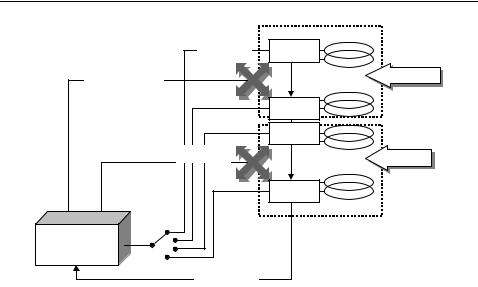
Figure 13.15 To achieve mutual decoupling the readers are switched alternately in timedivision multiplex operation
systems activate only one reader at a time, while the HF field of all other readers is switched off altogether. To achieve this, a multiplexer sends a start signal to one reader after the other in a cyclical sequence, which causes the addressed reader to switch on its HF field and check for the presence of a transponder (Figure 13.15). If the reader discovers a transponder, then it activates a busy signal. The busy signal tells the control unit to suppress the cyclical start signal for the duration of the busy signal. The active reader is now free to perform the data exchange it has begun with the transponder. After the end of this transaction, the active reader stops transmitting the busy signal, whereupon the multiplexer can continue its cyclical interrogation.
13.4Access Control
Electronic access control systems using data carriers are used to automatically check the access authorisation of individuals to buildings, (commercial or event) premises, or individual rooms. When designing such systems we must first differentiate between two fundamentally different systems with corresponding properties: online and offline systems.
13.4.1 Online systems
Online systems tend to be used where the access authorization of a large number of people has to be checked at just a few entrances. This is the case, for example, at the main entrances to office buildings and commercial premises. In this type of system, all terminals are connected to a central computer by means of a network.
13.4 ACCESS CONTROL |
359 |
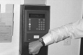
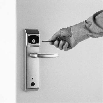
Figure 13.17 Offline terminal integrated into a doorplate. The lock is released by holding the authorized transponder in front of it. The door can then be opened by operating the handle. The door terminal can be operated for a year with four 1.5 V Mignon batteries and even has a real time clock that allows it to check the period of validity of the programmed data carrier. The terminals themselves are programmed by an infrared data transmission using a portable infrared reader (reproduced by permission of Hafele¨ GmbH, D-Nagold)
Only in the event of a data carrier being lost do key identifiers need to be deleted from the terminal in question using a suitable programming device.
Offline systems offer the following advantages over conventional lock systems with key and cylinder (Koch and Gaur, 1998) (see Figures 13.17 and 13.18):
•Early specification on a lock plan in the normal sense is not necessary. The system is initially coded for use as a building-site. When the site is handed over, the door terminals are recoded for commercial use by means of an infrared interface. Subsequent changes and expansions do not pose any problems.
•The option of programming time windows opens up further options: Temporary employees can receive a ‘three-month key’, the data carriers of cleaning staff can be given precise time specifications (for example Mondays and Fridays from 17.30 to 20.00).
•The loss of a key causes no problems. The data of the lost key is deleted from the read stations, a new key is programmed, and this key’s data is entered on the terminals in question.
360 |
13 EXAMPLE APPLICATIONS |
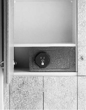
Figure 13.18 The hotel safe with integral offline terminal can only be opened by an authorised data carrier (reproduced by permission of (hotel-save is shown by the picture) Hafele¨ GmbH, D-Nagold)
13.4.3 Transponders
Access control using PVC cards has been around for a long time. Hole punched cards were used initially, which were superseded by infrared passes (IR barcode), magnetic strip passes, Wiegand passes (magnetic metal strips), and finally smart cards incorporating a microchip (Schmidhausler,¨ 1995; Virnich and Posten, 1992). The main disadvantage of these procedures is the inconvenience of the operating procedure due to the fact that the cards must always be inserted into a reader the right way round. Access control using contactless systems permits much greater flexibility because the transponder only needs to pass a short distance from the reader antenna. Passes can be made in the form of contactless smart cards, key rings, and even wristwatches.
A great advantage of contactless access control systems is that the reader is mainte- nance-free and is not influenced by dust, dirt or moisture. The antenna can be mounted ‘under plaster’, where it is completely invisible and protected against vandalism. Handsfree readers are also available for mounting in turnstiles or to increase convenience. In these designs, the transponders do not even need to be removed from the pocket or jacket clip.
Cat flaps operated by a transponder in the cat’s collar represent another application in the field of access control, as does the use of read-only transponders as anti-theft sensors for opening or closing doors and windows (Miehling, 1996).
13.5 TRANSPORT SYSTEMS |
361 |
13.5Transport Systems
13.5.1 Eurobalise S21
Although Europe is moving closer together cross-border transport still presents an obstacle to Europe’s railways. Different signals and train security systems force trains to incur the cost of carrying multiple sets of equipment on locomotives and tractive units. It is often necessary to expend precious time changing tractive vehicles at the border, burdening trains with a competitive disadvantage compared to flying or travelling by road (Lehmann, 1996).
For this reason, the European Union is backing the purchase of a unified European train security and control system, the ETCS (European Train Control System). The ETCS will facilitate interoperable cross-border traffic and improve the competitiveness of railways by implementing the latest train control technology.
The ETCS comprises four main systems:
•EURO-Cab A vehicle device, in which all connected elements are linked to the secure vehicle computer EVC (European Vital Computer) by a special ETCS bus system.
•EURO-Radio A GSM radio link between the vehicles and a radio centre by the track, the RBC (Radio Block Center).
•EURO-Loop A system for linear data transfer over distances up to several hundred metres. The system is based upon so-called leakage cable, i.e. coaxial cables for
which the sheathing is designed to be partially permeable to the electromagnetic field. The frequency ranges of this application lie between around 80 MHz and 1 GHz (Ernst, 1996). EURO-Loop is primarily used to transfer information for the evaluation of discretely transmitted data.
•EURO-Balise A system for the discrete transmission of data. Depending upon design, local data (location marking, gradient profiles, speed limits) or signal-related data for the route are transmitted to the vehicle (Lehmann, 1996).
The Eurobalise subsystem is particularly important, because it is a crucial prerequisite for the full introduction of the ETCS. In January 1995, after lengthy experiments, the technical framework data for the EURO-Balise were determined. It is an inductively coupled RFID system with anharmonic feedback frequency.
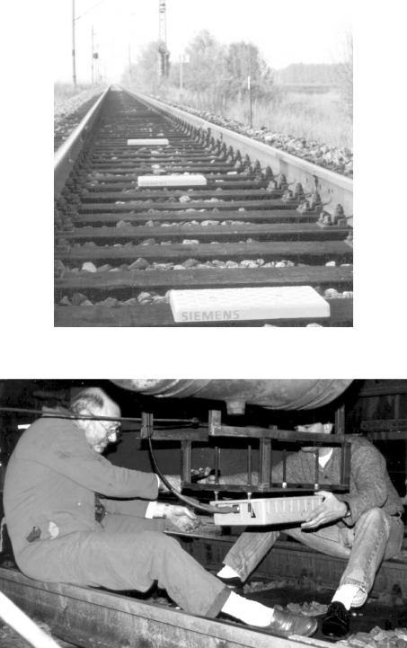
The power supply to the system is taken from a passing tractive unit by inductive coupling at the ISM frequency 27.115 MHz. Data is transferred to the tractive unit at 4.24 MHz, and the system is designed to reliably read the data telegram at train speeds of up to 500 km/h. See Figures 13.19 and 13.20, and Table 13.3.
Four different balise types have been developed by Siemens:
•Type 1 transmits a permanently programmed telegram.
•Type 2 transmits a telegram that can be programmed by the user via the contactless interface. For example, this may be line data such as gradient and speed profiles.

13.5 TRANSPORT SYSTEMS |
363 |
||
|
Table 13.3 Basic data for the Eurobalise |
||
|
|
|
|
|
Coupling |
Inductive |
|
|
|
|
|
|
Power transmission frequency, vehicle → balise |
27.115 MHz |
|
|
Data transmission frequency, balise → vehicle |
4.24 MHz |
|
|
Modulation type |
FSK |
|
|
Modulation index |
1 |
|
|
Data rate |
565 Kbit/s |
|
|
Telegram length |
1023 or 341-bit |
|
|
Useful data size |
863 or 216-bit |
|
|
Read distance |
230 to 450 mm |
|
|
Maximum sideways offset |
180 mm |
|
|
Coverage with snow, water, ore |
Non-critical |
|
|
|
|
|
•Type 3 transmits a telegram generated by a line device (transparent balise). Type 3 is primarily used in connection with signals.
•Type 4 makes it possible to download data as vehicles drive past.
13.5.2International container transport
International freight transport containers have been identified using the alphanumeric identification procedure specified in the international standard ISO 6346 since the end of the 1960s. This identification mark consists of four letters, the owner’s code, a six-digit numeric serial number and a test digit, and is painted onto the outside of the container at a specified position (Figure 13.21).
Almost all of the 7 million containers in use worldwide employ the identification procedures specified in this standard and thus have their own, unmistakable identification number. The process of manually recording the container identification number and entering it into the computer of a transhipment plant is extremely susceptible to errors. Up to 30% of identifications have been falsely recorded at some point. Automatic data transmission can help to solve this problem by the reading of a transponder attached to the container. In 1991 the international standard ISO 10374 was drawn up to provide a basis for the worldwide use of this technology.
The bands 888 to 889 MHz and 902 to 928 MHz (North America) and 2.4 to 2.5 GHz (Europe) are used as the operating frequencies for the transponders. The transponders must respond on all three of the frequency ranges used. Backscatter modulation (modulated reflection cross-section) with an FSK modulated subcarrier is the procedure used for the data transfer from the container to the reader. The subcarrier frequencies are 20 kHz and 40 kHz. A total of 128 bits (16 bytes) are transmitted within just 2 ms.
Figure 13.21 Container identification mark, consisting of owner’s code, serial number and a test digit