11.2 COMPONENTS OF A READER |
313 |
A different procedure is the rectification and thus demodulation of the (load) amplitude modulated voltage directly at the reader antenna. A sample circuit for this can be found in Section 11.3.
11.2.1.2Microwave systems – half duplex
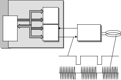
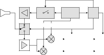
The main difference between microwave systems and low frequency inductive systems is the frequency synthesising: the operating frequency, typically 2.45 GHz, cannot be generated directly by the quartz oscillator, but is created by the multiplication (excitation of harmonics) of a lower oscillator frequency. Because the modulation is retained during frequency multiplication, modulation is performed at the lower frequency. See Figure 11.5.
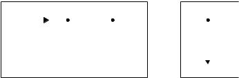
Some microwave systems employ a directional coupler to separate the system’s own transmission signal from the weak backscatter signal of the transponder (Integrated Silicon Design, 1996).
A directional coupler (Figure 11.6) consists of two continuously coupled homogeneous wires (Meinke and Gundlack, 1992). If all four ports are matched and power P1 is supplied to port 1 , then the power is divided between ports 2 and 3 , with no
|
|
Modulator Frequ. x n |
Output |
|
Quarz |
Oscillator |
module |
Directional coupler |
76 MHz |
|
|
2.45 GHz |
|
Transmission |
|
x 32 |
|
|
data |
|
|
|
|
|
|
|
|
|
Microwave |
|
|
Received |
|
receiver |
|
|
|
|
|
Antenna box |
data |
|
|
Amplifier |
|
|
|
Demodulator |
|
|
Figure 11.5 Block diagram of an HF interface for microwave systems
Generator power P1
HF interface |
|
|
Antenna |
Backscatter power P2 |
|
|
|
Transmitter |
1 |
3 |
0.99•P1 |
arm |
|
Directional |
|
|
Receiver |
0.01•P1 |
coupler |
|
|
arm |
2 |
4 |
0•P1 |
|
|
|
|
k•P2 |
Figure 11.6 Layout and |
operating principle of |
a directional |
coupler for a backscatter |
RFID system
power occurring at the decoupled port 4 . The same applies if power is supplied to port 3 , in which case the power is divided between ports 1 and 2 .
A directional coupler is described by its coupling loss:
ak = −20 · ln |P 2 /P 1 | |
(11.1) |
and directivity: |
|
aD = −20 · ln |P 4 /P 2 | |
(11.2) |
Directivity is the logarithmic magnitude of the ratio of undesired overcoupled power P4 to desired coupled power P2.
A directional coupler for a backscatter RFID reader should have the maximum possible directivity to minimise the decoupled signal of the transmitter arm at port 4 . The coupling loss, on the other hand, should be low to decouple the maximum possible proportion of the reflected power P2 from the transponder to the receiver arm at port 4 . When a reader employing decoupling based upon a directional coupler is commissioned, it is necessary to ensure that the transmitter antenna is well (anechoically) set up. Power reflected from the antenna due to poor adjustment is decoupled at port 4 as backwards power. If the directional coupler has a good coupling loss, even a minimal mismatching of the transmitter antenna (e.g. by environmental influences) is sufficient to increase the backwards travelling power to the magnitude of the reflected transponder power. Nevertheless, the use of a directional coupler gives a significant improvement compared to the level ratios achieved with a direct connection of transmitter output module and receiver input.
11.2.1.3Sequential systems – SEQ
In a sequential RFID system the HF field of the reader is only ever transmitted briefly to supply the transponder with power and/or send commands to the transponder.
The transponder transmits its data to the reader while the reader is not transmitting. The transmitter and receiver in the reader are thus active sequentially, like a walkietalkie, which also transmits and receives alternately. See Figure 11.7.
Quarz Oscillator Modulator Output module |
Antenna box |
Transmission |
|
data |
|
Received |
|
data |
|
Demodulator |
Amplifier |
Figure 11.7 HF interface for a sequential reader system
11.2 COMPONENTS OF A READER |
315 |
The reader contains an instantaneous switching unit to switch between transmitter and receiver mode. This function is normally performed by PIN diodes in radio technology.
No special demands are made of the receiver in an SEQ system. Because the strong signal of the transmitter is not present to cause interference during reception, the SEQ receiver can be designed to maximise sensitivity. This means that the range of the system as a whole can be increased to correspond with the energy range, i.e. the distance between reader and transponder at which there is just enough energy for the operation of the transponder.
11.2.1.4Microwave system for SAW transponders
A short electromagnetic pulse transmitted by the reader’s antenna is received by the antenna of the surface wave transponder and converted into a surface wave in a piezoelectric crystal. A characteristic arrangement of partially reflective structures in the propagation path of the surface wave gives rise to numerous pulses, which are transmitted back from the transponder’s antenna as a response signal (a much more comprehensive description of this procedure can be found in Section 4.3).
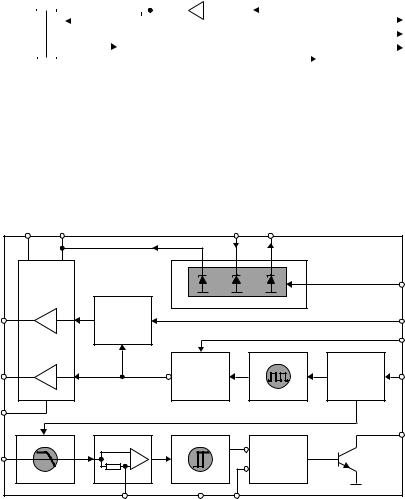
Due to the propagation delay times in the piezoelectric crystal the coded signal reflected by the transponder can easily be separated in the reader from all other electromagnetic reflections from the vicinity of the reader (see Section 4.3.3). The block diagram of a reader for surface wave transponders is shown in Figure 11.8.
A stable frequency and phase oscillator with a surface wave resonator is used as the high-frequency source. Using a rapid HF switch, short HF pulses of around 80 ns duration are generated from the oscillator signal, which are amplified to around 36 dBm (4 W peak) by the connected power output stage, and transmitted by the reader’s antenna.
If a SAW transponder is located in the vicinity of the reader it reflects a sequence of individual pulses after a propagation delay time of a few microseconds. The pulses
SAW
Clock
resonator
Antenna
90° 0°
|
|
|
|
|
|
|
|
|
|
|
|
|
|
|
|
|
|
|
|
|
|
|
|
I |
|
|
|
|
A/D |
|
|
I |
|
|
|
|
Micro- |
|
|
|
|
|
|
|
|
|
|
|
|
|
|
|
|
|
|
|
|
|
|
|
|
|
|
|
|
|
|
|
|
|
|
|
|
|
|
|
converter |
|
|
|
|
|
|
|
controller |
|
|
|
|
|
|
|
|
|
|
|
|
|
|
|
|
|
Q |
|
|
|
|
Q |
|
|
|
|
|
|
|
|
|
|
|
|
|
|
|
|
|
|
|
|
|
|
|
|
|
|
|
|
|
|
|
|
|
|
|
|
|
|
|
|
|
|
|
|
|
|
|
|
|
Figure 11.8 Block diagram of a reader for a surface wave transponder
received by the reader’s antenna pass through a low-noise amplifier and are then demodulated in a quadrature demodulator. This yields two orthogonal components (I and Q), which facilitate the determination of the phase angle between the individual pulses and between the pulses and the oscillator (Bulst et al., 1998). The information obtained can be used to determine the distance or speed between SAW transponder and reader and for the measurement of physical quantities (see Section 10.4.3).
To be more precise, the reader circuit in Figure 11.8 corresponds with a pulse radar, like those used in flight navigation (although in this application the transmission power is much greater). In addition to the pulse radar shown here, other radar types (for example FM-CW radar) are also in development as readers for SAW transponders.
11.2.2 Control unit
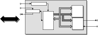
The reader’s control unit (Figure 11.9) performs the following functions:
•communication with the application software and the execution of commands from the application software;
•control of the communication with a transponder (master–slave principle);
•signal coding and decoding (Figure 11.10).
In more complex systems the following additional functions are available:
•execution of an anticollision algorithm;
•encryption and decryption of the data to be transferred between transponder and reader;
•performance of authentication between transponder and reader.
The control unit is usually based upon a microprocessor to perform these complex functions. Cryptological procedures, such as stream ciphering between transponder and reader, and also signal coding, are often performed in an additional ASIC module to relieve the processor of calculation intensive processes. For performance reasons the ASIC is accessed via the microprocessor bus (register orientated).
Vcc |
Power ON |
Data |
|
|
Data input |
|
|
|
|
|
RAM |
|
|
RS 232/485 |
Address |
|
|
ROM |
|
Data output |
|
|
|
|
|
|
|
|
P |
|
ASIC |
|
Application |
|
|
(crypto, |
HF interface |
|
|
Sig. cod.) |
|
software |
|
|
|
|
|
|
|
Figure 11.9 Block diagram of the control unit of a reader. There is a serial interface for communication with the higher application software
11.3 LOW COST CONFIGURATION — READER IC U2270B |
317 |
|
Address |
RAM |
|
|
|
ROM |
|
|
P |
ASIC |
HF |
|
Data |
|
(Crypto, |
|
|
interface |
|
|
Sig. cod.) |
|
|
|
Baseband signal:
HF signal (ASK):
Figure 11.10 Signal coding and decoding is also performed by the control unit in the reader
Data exchange between application software and the reader’s control unit is performed by an RS232 or RS485 interface. As is normal in the PC world, NRZ coding (8-bit asynchronous) is used. The baud rate is normally a multiple of 1200 Bd (4800 Bd, 9600 Bd, etc.). Various, often self-defined, protocols are used for the communication protocol. Please refer to the handbook provided by your system supplier.
The interface between the HF interface and the control unit represents the state of the HF interface as a binary number. In an ASK modulated system a logic ‘1’ at the modulation input of the HF interface represents the state ‘HF signal on’; a logic ‘0’ represents the state ‘HF signal off’ (further information in Section 10.1.1).
11.3Low Cost Configuration – Reader IC U2270B
It is typical of applications that use contactless identification systems that they require only a few readers, but a very large number of transponders. For example, in a public transport system, several tens of thousands of contactless smart cards are used, but only a few hundred readers are installed in vehicles. In applications such as animal identification or container identification, there is also a significant difference between the number of transponders used and the corresponding number of readers. There are also a great many different systems, because there are still no applicable standards for inductive or microwave RFID systems. As a result, readers are only ever manufactured in small batches of a few thousand.
Electronic immobilisation systems, on the other hand, require a vast number of readers. Because since 1995 almost all new cars have been fitted with electronic immobilisation systems as standard, the number of readers required has reached a completely new order of magnitude. Because the market for powered vehicles is also very price sensitive, cost reduction and miniaturisation by the integration of a small number of
functional modules has become worth pursuing. Because of this, it is now possible to integrate the whole analogue section of a reader onto a silicon chip, meaning that only a few external components are required. We will briefly described the U2270B as an example of such a reader IC.
The reader IC U2270B by TEMIC serves as a fully integrated HF interface between a transponder and a microcontroller (Figure 11.11).
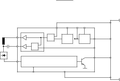
The IC contains the following modules: on-chip oscillator, driver, received signal conditioning and an integral power supply (Figure 11.12).
Transponder / TAG |
|
|
|
|
|
|
|
|
Read / write base station |
|
|
|
|
|
|
|
|
|
|
|
|
|
|
|
|
|
|
|
|
|
|
|
|
|
|
|
|
|
Carrier |
|
|
|
|
|
|
|
|
|
Transp. |
|
|
|
|
|
|
|
|
|
|
|
|
|
|
|
|
|
|
|
|
|
|
|
|
|
|
|
|
|
|
|
|
|
|
|
|
|
|
|
|
|
|
Osc |
|
|
|
|
|
|
|
|
|
|
|
IC |
|
|
|
|
|
|
|
|
|
|
|
|
|
|
|
|
|
enable |
|
|
|
|
|
|
|
Unlock |
|
|
|
|
|
|
|
|
|
|
|
|
|
|
|
|
|
|
|
|
|
|
|
|
|
|
|
|
|
e5530 |
|
|
|
|
|
RF field |
|
|
|
|
|
|
U2270B |
|
|
|
|
MCU |
|
|
|
|
|
|
|
|
typ. 125 kHz |
|
|
|
|
|
|
|
|
|
|
|
|
|
system |
|
|
|
|
|
|
|
|
|
|
|
|
|
|
|
|
|
|
|
|
|
|
|
|
e5550 |
|
|
|
|
|
|
|
|
|
|
|
|
|
NF read channel |
Data |
|
|
|
|
|
|
|
|
|
e5560 |
|
|
|
|
|
|
|
|
|
|
|
|
|
|
|
|
|
|
|
|
|
|
|
|
|
|
|
|
|
|
|
|
|
|
|
|
output |
|
|
|
|
|
|
|
|
|
|
|
|
|
|
|
|
|
|
|
|
|
|
|
|
|
|
|
|
|
|
|
|
|
|
|
|
|
|
|
|
|
|
|
|
|
|
|
|
|
|
|
|
|
|
|
|
|
|
|
|
|
|
|
|
|
|
|
|
|
|
|
|
|
|
|
|
|
|
|
|
|
|
|
|
|
|
|
|
|
|
|
|
|
|
TK5530-PP |
|
|
|
|
|
|
|
|
|
|
|
|
|
|
|
|
|
|
|
|
|
9300 |
|
|
|
e5530-GT |
|
|
|
|
|
|
|
|
|
|
|
|
|
|
|
|
|
|
|
|
|
|
|
|
|
|
TK5550-PP |
|
|
|
|
|
|
|
|
|
|
|
|
|
|
|
|
|
|
|
|
|
|
|
|
|
|
TK5560-PP |
|
|
|
|
|
|
|
|
|
|
|
|
|
|
|
|
|
|
|
|
|
|
|
|
|
Figure 11.11 The low-cost reader IC U2270B represents a highly integrated HF interface. The control unit is realised in an external microprocessor (MCU) (reproduced by permission of TEMIC Semiconductor GmbH, Heilbronn)
DVS |
VEXT |
|
VS |
VBatt |
|
|
|
|
|
|
Standby |
|
|
Power supply |
|
|
|
COIL1 |
=1 |
|
|
|
MS |
|
|
|
|
|
CFE |
COIL2 |
|
& |
|
Frequency |
RF |
|
|
adjustment |
Driver |
|
|
|
Oscillator |
|
|
|
|
|
|
DGND |
|
|
|
|
|
|
|
|
|
|
Output |
|
Amplifier |
|
|
|
|
Input |
|
|
|
& |
|
Lowpass filter |
Schmitt trigger |
|
|
|
|
HIPASS |
GND |
OE |
|
9692 |
|
|
|
Figure 11.12 Block diagram of the reader IC U2270B. The transmitter arm consists of an oscillator and driver to supply the antenna coil. The receiver arm consists of filter, amplifier and a Schmitt trigger (reproduced by permission of TEMIC Semiconductor GmbH, Heilbronn)
11.4 CONNECTION OF ANTENNAS FOR INDUCTIVE SYSTEMS |
319 |
|
|
|
|
|
|
Demodulator |
|
|
|
|
|
U2270B |
|
|
|
|
|
|
|
|
|
|
|
|
|
|
|
|
|
|
|
|
|
|
|
|
|
|
|
|
|
|
|
|
|
|
|
|
|
|
|
|
|
|
|
|
|
|
|
|
|
|
|
|
|
|
|
|
|
|
|
|
|
|
|
|
|
|
From reader |
R1 |
D1 |
|
|
|
C1 |
|
|
R2 |
C2 |
|
|
|
Ri |
|
|
|
|
|
|
|
|
4.7 k |
|
|
|
|
|
|
|
|
|
|
|
|
|
|
|
|
|
|
|
|
|
|
|
|
|
1.5 n |
|
|
470 k |
680 p |
|
|
|
220 k |
antenna |
|
|
|
|
|
|
|
|
|
|
|
|
|
|
|
|
|
|
|
|
|
|
|
|
|
|
|
|
|
|
|
|
|
|
|
|
|
|
|
|
|
|
|
|
|
|
|
|
|
|
|
|
|
|
|
|
Bias
Figure 11.13 Rectification of the amplitude modulated voltage at the antenna coil of the reader (reproduced by permission of TEMIC Semiconductor GmbH, Heilbronn)
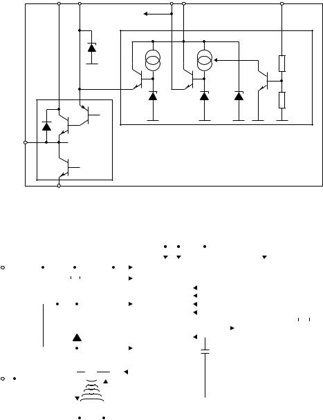
The on-chip oscillator generates the operating frequency in the range 100–150 kHz. The precise frequency is adjusted by an external resistor at pin RF. The downstream driver generates the power required to control the antenna coil as push–pull output. If necessary, a baseband modulation signal can be fed into pin CFE as a TTL signal and this switches the HF signal on/off, generating an ASK modulation.
The load modulation procedure in the transponder generates a weak amplitude modulation of the reader’s antenna voltage. The modulation in the transponder occurs in the baseband, i.e. without the use of a subcarrier. The transponder modulation signal can be reclaimed simply by demodulating the antenna voltage at the reader using a diode. The signal, which has been rectified by an external diode and smoothed using an RC low-pass filter, is fed into the ‘Input’ pin of the U2270B (Figure 11.13). Using a downstream Butterworth low-pass filter, an amplifier module and a Schmitt trigger, the demodulated signal is converted into a TTL signal, which can be evaluated by the downstream microprocessor. The time constants of the Butterworth filter are designed so that a Manchester or bi-phase code can be processed up to a data rate of fosc/25 (approximately 4800 bit/s) (TEMIC, 1977).
A complete application circuit for the U2270B can be found in the following chapter.
11.4Connection of Antennas for Inductive Systems
Reader antennas in inductively coupled RFID systems generate magnetic flux , which is used for the power supply of the transponder and for sending messages between the reader and the transponder. This gives rise to three fundamental design requirements for a reader antenna:
•maximum current i1 in the antenna coil, for maximum magnetic flux ;
•power matching so that the maximum available energy can be used for the generation of the magnetic flux;
•sufficient bandwidth for the undistorted transmission of a carrier signal modulated with data.
Depending upon the frequency range, different procedures can be used to connect the antenna coil to the transmitter output of the reader: direct connection of the antenna coil to the power output module using power matching or the supply of the antenna coil via coaxial cable.
11.4.1 Connection using current matching
In typical low cost readers in the frequency range below 135 kHz, the HF interface and antenna coil are mounted close together (a few centimetres apart), often on a single printed circuit board. Because the geometric dimensions of the antenna supply line and antenna are smaller than the wavelength of the generated HF current (2200 m) by powers of ten, the signals may be treated as stationary for simplification. This means that the wave characteristics of a high frequency current may be disregarded. The connection of an antenna coil is thus comparable to the connection of a loudspeaker to an NF output module from the point of view of circuitry.
The reader IC U2270B, which was described in the preceding section, can serve as an example of such a low cost reader (Figures 11.14–11.16).
Figure 11.14 shows an example of an antenna circuit. The antenna is fed by the push–pull bridge output of the reader IC. In order to maximise the current through the antenna coil, a serial resonant circuit is created by the serial connection of the antenna coil LS to a capacitor CS and a resistor RS. Coil and capacitor are dimensioned such that the resonant frequency f0 is as follows at the operating frequency of the reader:
|
f0 |
= |
|
√ |
1 |
(11.3) |
|
2π |
Ls · Cs |
|
|
|
|
|
The coil current is then determined exclusively by the series resistor RS.
|
CFE |
RF |
VS |
VBatt |
OSC |
95 9860 |
enable |
COIL1 |
Driver |
|
|
Power |
Standby |
|
& |
Oscillator |
|
|
|
|
supply |
|
|
|
|
|
|
COIL2 |
= 1 |
|
|
|
MS |
|
|
|
|
|
U2270B |
|
|
m C |
|
|
|
|
|
|
|
|
|
Output |
|
|
|
|
|
CODE |
Input |
NF read channel |
|
|
|
|
|
|
|
|
|
|
GAIN |
OE |
|
|
Ouput |
|
|
|
|
|
enable |
Figure 11.14 Block diagram for the reader IC U2270B with connected antenna coil at the push–pull output (reproduced by permission of TEMIC Semiconductor GmbH, Heilbronn)
11.4 CONNECTION OF ANTENNAS FOR INDUCTIVE SYSTEMS |
321 |
DVS |
VEXT |
VS |
VBatt |
Standby |
|
|
Internal supply |
|
|
|
9 V |
|
|
25 kW |
|
|
|
|
|
|
|
|
12 kW |
|
|
6 V |
6 V |
18 V |
|
|
|
PS |
|
COILx |
|
|
|
|
|
DRV |
|
|
|
DGND |
|
|
|
11413 |
|
|
|
|
Figure 11.15 Driver circuit in the reader IC UU2270B (reproduced by permission of TEMIC Semiconductor GmbH, Heilbronn)
|
|
|
|
|
|
|
|
|
|
|
|
|
|
|
|
|
|
|
|
|
|
|
|
|
|
|
|
|
|
|
|
|
|
|
|
|
|
|
|
|
|
|
|
|
|
|
|
|
|
|
110 kW |
|
|
|
5 V |
5 V |
|
|
|
|
|
|
|
|
|
|
|
|
|
|
VBatt |
VEXTVS |
|
|
|
|
|
|
|
|
|
|
|
|
VDD |
|
|
|
|
|
|
|
|
|
|
|
|
|
|
|
|
|
|
|
|
|
|
|
|
|
|
|
|
|
|
|
|
|
|
|
|
|
|
|
|
|
|
|
|
|
|
|
|
|
|
|
|
|
|
|
|
|
|
|
|
|
|
|
|
|
|
|
|
|
|
|
|
|
|
|
|
|
|
|
|
|
|
|
|
|
|
|
|
|
|
|
|
U2270B |
|
|
|
|
|
|
|
|
|
|
|
|
M44C260 |
|
|
|
|
|
|
|
|
|
|
|
|
|
|
|
|
|
47 nF |
|
|
|
|
|
22 mF |
|
|
|
|
DVS |
|
|
|
|
|
|
|
|
|
|
|
|
|
|
|
|
|
|
|
|
|
|
|
|
|
|
|
|
|
|
|
|
|
|
|
|
|
|
|
|
|
RF |
|
|
|
|
|
|
|
|
|
|
|
|
|
|
|
|
|
|
|
|
|
|
|
|
|
|
|
|
|
|
|
|
|
|
|
|
|
|
|
|
|
|
|
|
680 pF |
|
|
|
|
|
|
|
|
|
|
|
|
|
|
|
|
|
|
|
|
|
|
|
|
|
|
|
|
|
|
|
|
|
|
|
|
|
|
|
|
|
|
|
|
|
|
|
|
|
|
|
|
|
|
|
|
|
|
|
|
|
|
|
|
|
|
|
|
|
|
|
|
|
|
|
|
|
|
|
|
|
|
|
|
|
|
|
|
|
|
|
|
|
|
|
|
|
|
|
|
|
|
|
|
Input |
|
|
|
|
MS |
|
|
|
|
|
|
|
|
|
|
BP00 |
|
|
|
|
|
|
|
|
|
|
|
|
|
|
|
|
|
|
|
|
|
|
|
|
|
|
|
|
|
|
|
|
|
|
|
|
|
|
|
|
|
|
|
|
|
|
|
|
|
|
|
|
|
|
|
|
|
|
|
|
|
|
|
|
|
|
|
|
|
|
|
|
|
|
|
|
|
|
|
|
|
|
|
|
|
|
|
|
|
|
|
|
|
CFE |
|
|
|
|
|
|
|
|
|
|
BP01 |
|
|
|
osc IN |
|
|
32 kHz |
|
|
|
|
|
|
|
|
|
|
|
|
|
|
|
|
|
|
|
|
|
|
|
|
|
|
|
|
|
|
|
|
|
|
|
|
|
|
|
|
|
|
|
|
|
|
|
|
|
|
|
|
|
|
|
|
|
|
|
|
|
|
|
|
|
|
|
|
|
|
|
|
|
|
|
|
|
4.7 kW |
|
|
|
|
|
|
|
|
OE |
|
|
|
|
|
|
|
|
|
|
BP02 |
|
|
|
|
|
|
|
|
|
|
|
|
|
|
|
|
|
|
|
|
|
|
|
|
|
|
|
|
|
|
|
|
|
|
Standby |
|
|
|
|
|
|
|
|
|
|
BP03 |
|
|
|
|
|
|
|
|
|
|
|
|
|
|
|
|
|
|
|
|
|
|
|
|
|
|
|
|
|
|
|
|
|
|
|
|
|
|
|
|
|
|
|
|
|
|
|
|
|
|
|
|
|
|
|
|
|
|
|
|
|
|
|
|
|
|
|
|
|
|
|
|
|
|
|
|
|
|
|
|
|
|
|
|
|
|
|
|
|
|
|
|
|
|
Output |
|
|
|
|
|
|
|
|
|
|
BP10 |
|
|
osc OUT |
|
|
|
|
|
|
|
470 kW |
|
|
|
|
|
|
|
|
|
|
|
|
|
|
1N4148 |
COIL2 |
|
|
|
Gain |
|
|
|
|
|
|
|
|
|
|
|
|
|
|
|
|
|
|
|
|
|
|
|
|
|
|
|
|
|
|
|
|
|
|
|
|
|
|
|
|
|
|
|
|
|
|
|
|
|
|
|
|
|
|
|
|
|
|
|
|
|
|
|
|
|
|
|
|
|
|
|
|
|
|
|
|
|
|
|
|
|
|
|
|
|
|
|
|
|
|
|
|
|
|
|
|
|
|
|
|
|
|
|
|
|
|
|
|
|
|
|
|
|
|
|
|
|
|
|
|
|
|
|
|
|
|
|
|
|
|
Micro |
|
|
|
|
|
|
|
|
|
|
|
|
|
|
|
|
|
|
|
1.5 nF |
|
|
|
|
|
1.2 nF |
|
|
Read/write |
|
|
|
|
100 nF |
|
|
|
|
|
|
C31 |
|
|
|
|
|
|
|
|
|
|
|
1.35 mH R |
COIL1 |
circuit |
|
|
|
|
|
|
|
|
|
|
controller |
|
|
|
|
|
|
|
|
|
|
|
|
|
|
|
|
|
|
|
|
|
|
|
|
|
|
|
|
|
|
|
|
|
|
|
|
|
|
|
|
|
|
|
|
|
|
|
|
|
|
|
|
|
|
|
|
|
|
|
|
|
|
|
|
|
|
|
|
|
|
|
|
|
|
|
|
|
|
|
|
|
|
|
|
|
|
|
|
|
|
|
|
|
|
|
|
|
|
|
|
|
|
|
|
|
|
|
|
|
|
|
|
|
|
|
|
|
|
|
|
|
|
|
|
|
|
|
|
|
|
|
|
|
|
|
|
|
|
|
|
|
|
|
|
|
|
|
|
|
|
|
|
|
|
|
Power |
|
|
|
|
|
|
|
|
|
|
Data |
DGND |
|
GND |
|
|
|
|
|
|
|
|
|
|
|
|
VSS |
|
|
|
|
|
|
|
|
|
|
|
|
|
|
|
|
|
|
|
|
|
|
|
|
|
|
|
|
|
|
|
|
|
|
|
|
|
|
|
|
|
|
|
|
|
|
|
|
|
|
|
|
|
|
|
|
|
|
|
|
|
|
|
|
|
|
|
|
|
|
|
|
|
|
|
|
|
|
|
|
|
|
|
|
|
|
|
|
|
|
|
|
|
|
|
|
|
|
|
|
|
|
|
|
|
|
|
|
|
|
|
|
|
|
|
|
|
|
|
|
|
|
|
|
|
|
|
|
|
|
|
|
|
|
|
|
|
|
|
|
|
|
|
|
|
|
|
|
|
|
|
|
|
|
|
|
|
|
|
|
|
|
|
|
|
|
|
|
|
|
|
|
|
|
|
|
|
|
|
|
|
|
|
|
|
|
|
|
|
|
|
|
|
|
|
|
|
|
|
|
|
|
|
|
|
|
|
|
|
|
|
|
|
|
|
|
|
|
|
|
|
|
|
|
|
|
|
|
|
|
|
|
|
|
|
|
|
|
|
|
|
|
|
|
|
|
|
|
|
|
|
|
|
|
|
|
|
|
|
|
|
|
|
|
|
|
|
|
|
|
|
|
|
|
|
|
|
|
|
|
|
|
|
|
|
|
|
|
|
|
|
|
|
|
|
|
|
|
|
|
|
|
|
|
|
|
|
|
|
|
|
|
|
|
|
|
|
|
|
|
|
|
|
|
|
|
|
|
|
|
|
|
|
|
|
|
|
|
|
|
|
|
|
|
|
|
|
|
|
|
|
|
|
|
|
|
|
|
|
|
|
|
|
|
|
|
|
|
|
|
|
|
|
|
|
|
|
|
|
|
|
|
|
|
|
|
|
|
|
|
|
|
|
|
|
|
|
|
|
|
|
|
|
|
|
|
|
|
|
|
|
|
|
|
|
|
|
|
|
|
|
|
|
|
|
|
|
|
|
|
|
|
|
|
|
|
|
|
|
|
|
|
|
|
|
|
|
|
|
|
|
|
|
|
|
|
|
|
|
|
|
|
|
|
|
|
|
|
|
|
|
|
|
|
|
|
|
|
|
|
|
|
|
|
|
|
|
|
|
|
|
|
|
|
|
|
|
|
|
|
|
|
|
|
|
|
|
|
|
|
|
|
|
|
|
|
|
|
|
|
|
|
|
|
|
|
|
|
|
|
|
|
|
|
|
|
|
|
|
|
|
|
|
|
|
|
|
|
|
|
|
|
|
|
|
|
|
|
|
|
|
|
|
|
|
|
|
|
|
|
|
e5530 |
|
|
|
|
|
|
|
|
|
|
|
|
|
|
|
|
|
|
|
|
|
125 kHz |
|
|
|
|
|
|
|
|
|
|
|
|
|
|
|
|
|
|
|
|
|
|
|
|
|
|
|
|
|
|
|
|
|
|
|
|
|
|
|
|
|
|
|
|
|
|
|
|
|
|
|
|
|
|
|
|
|
|
|
|
|
|
|
|
|
|
|
|
|
|
|
|
|
|
|
|
|
|
|
|
|
|
|
|
|
|
|
Transponder |
|
|
|
|
|
|
|
|
|
|
|
|
|
|
|
|
|
|
|
|
|
|
|
|
|
|
|
|
|
|
|
|
|
|
|
|
|
|
|
|
|
|
|
|
|
|
|
|
|
|
|
|
|
|
|
|
|
|
|
|
|
|
|
|
|
|
|
|
|
|
|
|
|
|
|
|
|
|
|
|
|
|
|
|
|
|
|
|
|
|
|
|
|
|
|
TK5530 |
|
|
|
|
|
|
|
|
|
|
|
|
|
|
|
|
|
|
|
|
|
|
12635 |
|
|
|
|
|
|
|
|
|
|
|
|
|
|
|
|
|
|
|
|
|
|
|
|
|
|
|
|
|
|
|
|
|
|
|
|
|
|
|
|
|
|
|
|
|
|
|
|
|
|
|
|
|
|
|
|
Figure 11.16 Complete example application for the low cost reader IC U2270B (reproduced by permission of TEMIC Semiconductor GmbH, Heilbronn)
11.4.2 Supply via coaxial cable
At frequencies above 1 MHz, or in the frequency range 135 kHz if longer cables are used, the HF voltage can no longer be considered stationary, but must be treated as an electromagnetic wave in the cable. Connecting the antenna coil using a long, unshielded two core wire in the HF range would therefore lead to undesired effects, such as power reflections, impedance transformation and parasitic power emissions, due to the wave nature of a HF voltage. Because these effects are difficult to control when they are not exploited intentionally, shielded cable — so-called coaxial cable — is normally used in radio technology. Sockets, plugs and coaxial cable are uniformly designed for a cable impedance of 50 and, being a mass produced product, are correspondingly cheap. RFID systems generally use 50 components.
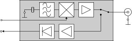
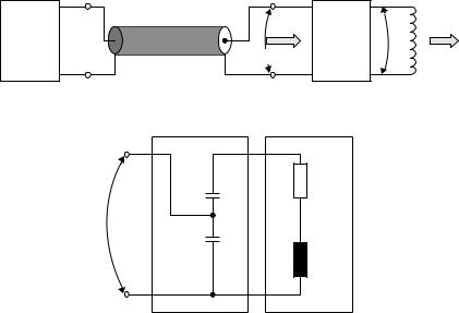
The block diagram of an inductively coupled RFID system using 50 technology shows the most important HF components (Figure 11.17).
The antenna coil L1 represents an impedance ZL in the operating frequency range of the RFID system. To achieve power matching with the 50 system, this impedance must be transformed to 50 (matched) by a passive matching circuit. Power transmission from the reader output module to the matching circuit is achieved (almost) without losses or undesired radiation by means of a coaxial cable.
A suitable matching circuit can be realised using just a few components. The circuit illustrated in Figure 11.18, which can be constructed using just two capacitors, is very simple to design (Suckrow, 1997). This circuit is used in practice in various 13.56 MHz RFID systems.
Figure 11.19 shows a reader with an integral antenna for a 13.56 MHz system. Coaxial cable has not been used here, because a very short supply line can be realised
Reader |
Coaxial cable 50 Ω |
|
|
PA |
P1 |
Matching |
P2 |
(power |
|
ZL |
|
circuit |
amplifier) |
Zin = 50 Ω |
|
|
|
50 Ω |
|
|
L1 |
|
|
|
Figure 11.17 Connection of an antenna coil using 50 technology
Matching circuit |
Antenna coil |
Figure 11.18 Simple matching circuit for an antenna coil