9.2 CONTACTLESS SMART CARDS |
241 |
To this end the card incorporates a large area antenna coil typically with 3–6 windings of wire (see Figures 2.11 and 2.12).
The magnetic field generated by the reader must be within the range 1.5 A/m ≤ H ≤ 7.5 A/m. Thus the interrogation field strength Hmin of a proximity coupling smart card is automatically Hmin ≤ 1.5 A/m. This is the only way to ensure that a smart card with an interrogation field strength Hmin = 1.5 A/m can be read by a reader that generates a field strength of just 1.5 A/m (e.g. a portable, battery operated reader with a correspondingly lower transmission power), at least at distance x = 0 from the transmission antenna (smart card in contact) (Berger, 1998).
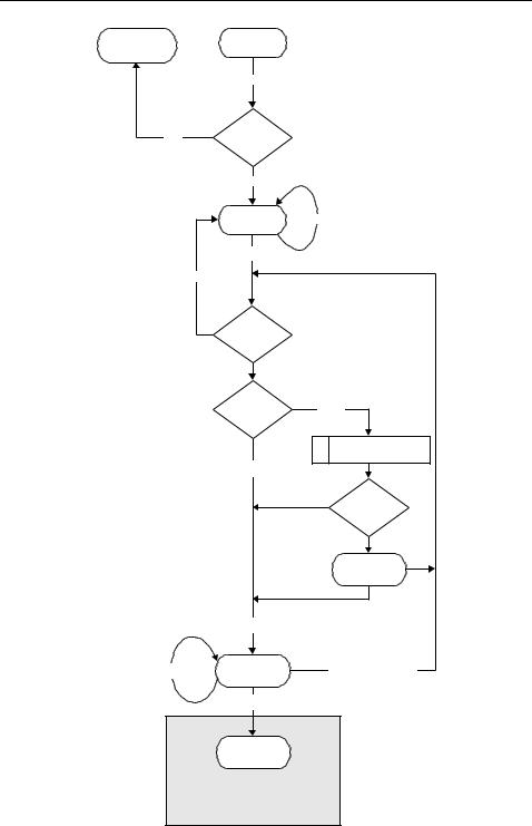
If the field strength curve of a reader and the interrogation field strength of a proximity coupling smart card are known, then the range of the system can be calculated. The field strength curve of a typical reader in accordance with ISO 14443 is shown in Figure 9.11 (see Section 4.1.1.1). In this case, a smart card interrogation field strength of 1.5 A/m results in a range of 10 cm.
Unfortunately it was not possible to agree to a common communication interface in the development of this standard. For this reason, two completely different procedures for the data transfer between reader and proximity coupling smart card have found a place in ISO 14443 — Type A and Type B. A smart card only has to support one of the two communication procedures. A reader conforming to the standard, on the other hand, must be able to communicate equally well by both procedures, and thus support all smart cards. This means that the reader must switch between the two communication procedures (polling) periodically during ‘idle’ mode (‘wait for smart card’).
However, the reader may not switch between the two procedures during an existing communication relationship between reader and card.
8
Hmax = 7.5 A/m
6
Figure 9.11 Typical field strength curve of a reader for proximity coupling smart cards (antenna current i1 = 1A, antenna diameter D = 15 cm, number of windings N = 1)
242 |
|
|
|
|
|
|
|
|
|
|
|
|
|
9 |
STANDARDISATION |
|
|
|
1 |
|
0 |
|
0 |
0 |
|
1 |
|
|
1 |
|
|
|
|
|
|
0 |
|
|
|
|
|
|
|
|
|
|
|
|
|
|
|
|
|
|
|
|
|
|
|
|
|
|
|
|
|
|
|
|
|
|
|
|
|
|
|
|
|
|
|
|
|
|
|
|
|
|
|
|
|
|
|
|
|
|
|
|
|
|
|
|
|
|
|
|
|
|
|
|
|
|
|
|
|
|
|
|
|
|
|
|
|
|
|
|
|
|
|
|
|
|
|
|
|
|
|
|
|
|
|
|
|
|
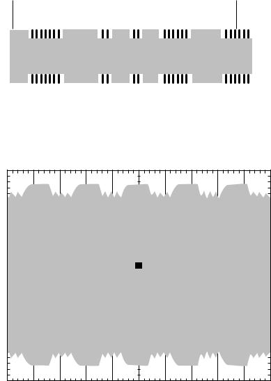
Figure 9.12 Modulation procedure for proximity coupling smart cards in accordance with ISO 14443 — Type A: Top: Downlink — ASK 100% with modified Miller coding (voltage path at the reader antenna). Bottom: Uplink — load modulation with ASK modulated 847 kHz subcarrier in Manchester coding (voltage path at the transponder coil)
Tek run: 10.0 MS/s |
Sample |
|
[ |
.............................T............................. |
] |
T
|
|
|
|
|
|
|
|
|
|
|
|
|
|
|
|
|
|
|
|
|
|
|
|
|
|
|
|
|
|
|
|
|
|
|
|
|
|
|
|
|
|
|
|
|
|
|
|
|
|
|
|
|
|
|
|
|
|
|
|
|
|
|
|
|
|
|
|
|
|
|
|
|
|
|
|
|
|
|
|
|
|
|
|
|
|
|
|
|
|
|
|
|
|
|
|
|
|
|
|
|
|
|
|
|
|
|
|
|
|
|
M 5.00 s Ch2 S |
|
|
|
|
|
|
|
|
|
Ch 1 |
|
|
2.00 V |
|
|
|
|
|
|
|
|
|
|
|
|
|
2.4 V |
|
|
|
|
|
|
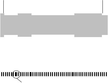
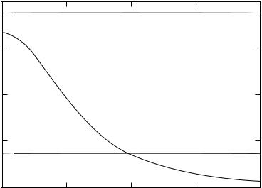
Figure 9.13 The oscillogram of a signal generated at the reader antenna by a Type A card using load modulation with an ASK modulated subcarrier
9.2 CONTACTLESS SMART CARDS |
243 |
Communication interface — Type A In type A cards 100% ASK modulation with modified Miller coding (Figure 9.12) is defined as the modulation procedure used for the transfer of data from reader to card. In order to guarantee a continuous power supply to the card the length of the blanking intervals is just 2–3 µs. The requirements of the transient response and transient characteristics of the HF signal generated by the reader in the blanking intervals are described in detail in the standard. A load modulation procedure with subcarrier is used for data transfer from the smart card to the reader. The subcarrier frequency fH = 847 kHz (13.56 MHz/16). The modulation of the subcarrier is performed by on/off keying of the subcarrier using a Manchester coded data stream. See Figures 9.12 and 9.13.
In both transfer directions the baud rate fBd = 106 kBit/s (13.56 MHz/128).
Communication interface — Type B In Type B cards 10% ASK modulation
(Figure 9.14) is used as the modulation procedure for the data transfer from reader to card. A simple NRZ coding is used for bit coding. The transient response and transient characteristics of the HF signal in the 0/1 transitions are precisely defined in the standard and requirements of the quality of the transmission antenna can be derived from this (see Section 11.4.1.3).
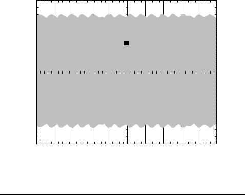
For data transfer from the smart card to the reader load modulation with a subcarrier is also used for the Type B card. The subcarrier frequency fH = 847 kHz (13.56 MHz/16). The subcarrier is modulated by 180◦ phase shift keying (BPSK) of the subcarrier using the NRZ coded data stream. See Figure 9.15.
In both transmission directions the baud rate fBd = 106 kBit/s (13.56 MHz/128).
Phase shift: Φ = ±180°
Figure 9.14 Modulation procedure for proximity coupling smart cards in accordance with ISO 14443 — Type B. Top: Downlink — ASK 10% with NRZ coding (voltage path at the reader antenna). Bottom: Uplink — load modulation with BPSK modulated 847 kHz subcarrier in NRZ coding (voltage path at the transponder coil)
244 |
|
9 STANDARDISATION |
Tek run: 25.0 MS/s |
Sample |
|
[ |
.............................T............................. |
] |
T
|
|
|
|
M 2.00 s Ch2 S |
|
|
|
|
|
|
|
|
Ch 1 |
2.00 V |
2.4 V |
|
|
|
Figure 9.15 The oscillogram of a signal generated at the reader antenna by a Type B card using load modulation with BPSK modulated subcarrier
Table 9.7 Data transfer reader (PCD) → smart card (PICC) (Berger, 1998)
PCD → PICC |
Type A |
|
Type B |
Modulation |
ASK 100% |
ASK 10% (modulation index 8%–12%) |
Bit coding |
Modified Miller code |
NRZ code |
Synchronisation |
At bit level (start-of-frame, |
1 start and 1 stop bit per bye |
|
end-of-frame marks) |
(specification in Part 3) |
Baud rate |
106 kBd |
106 kBd |
|
Table 9.8 Data transfer smart card (PICC) → reader (PCD) (Berger, 1998) |
PICC → PCD |
Type A |
|
Type B |
Modulation |
Load modulation with subcarrier |
|
Load modulation with subcarrier |
|
847 kHz, ASK modulated |
|
847 kHz, BPSK modulated |
Bit coding |
Manchester code |
|
NRZ code |
Synchronisation |
1 bit frame synchronisation |
|
1 start and 1 stop bit per byte |
|
(start-of-frame, end-of-frame marks) |
(specification in Part 3) |
Baud rate |
106 kBd |
|
106 kBd |
|
|
|
|
Overview To sum up, the parameters shown in Tables 9.7 and 9.8 exist for the physical interface between reader and smart card of an RFID system in accordance with ISO 14443-2.

9.2 CONTACTLESS SMART CARDS |
245 |
9.2.2.3 Part 3 – Initialisation and anticollision
If a proximity coupling smart card enters the interrogation field of a reader, then a communication relationship must first of all be built up between reader and smart card, taking into consideration the fact that there may be more than one smart card within the interrogation zone of this reader and that the reader may already be in communication with another card. This part of the standard therefore first describes the structure of the protocol frames from the basic elements defined in Part 2 — data bit, start-of-frame and end-of-frame marks — and the anticollision procedure used for the selection of an individual card. Since the different modulation procedure for Type A and Type B also requires a different frame structure and anticollision procedure, the divide between the two types A and B is reflected in Part 3 of the standard.
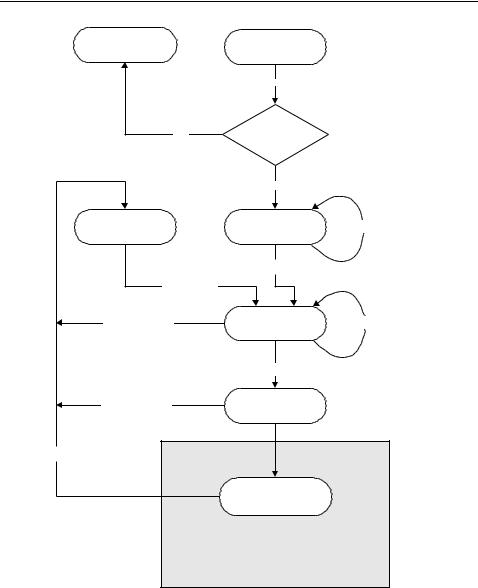
Type A card As soon as a Type A smart card enters the interrogation zone of a reader and sufficient supply voltage is available, the card’s microprocessor begins to operate. After the performance of some initialisation routines — if the card is a dual interface card these include checking whether the card is in contactless or contact mode — the card is put into so-called IDLE mode. At this point the reader can exchange data with another smart card in the interrogation zone. However, smart cards in the IDLE state may never react to the reader’s data transmission to another smart card (‘any command’) so that an existing communication is not interrupted.
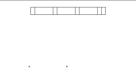
If, when the card is in IDLE mode, it receives a valid REQA command (Request-A), then an ATQA block (Answer to Request) is sent back to the reader in response (Figure 9.16). In order to ensure that data destined for another card in the interrogation field of the reader is not falsely interpreted as a REQA command, this command is made up of only 7 data bits (Figure 9.17). The ATQA block sent back, on the other hand, consists of 2 bytes and is returned in a standard frame.
After the card has responded to the REQA command it is put into the READY state. The reader has now recognised that at least one card is in the interrogation field and begins the anticollision algorithm by transmitting a SELECT command. The anticollision procedure used here is a dynamic binary search tree algorithm.4 A bit-oriented frame is used for the transfer of the search criterion and the card’s response, so that the transmission direction between reader and card can be reversed after a desired number of bits have been sent. The NVB (number of valid bits) parameter of the SELECT command specifies the current length of the search criterion.
The length of a single serial number is 4 bytes. If a serial number is detected by the anticollision algorithm, then the reader finally sends the full serial number (NVB = 40 h) in the SELECT command, in order to select the card in question. The card with the detected serial number confirms this command by an SAK (SELECT-Acknowledge) and is thereby put into ACTIVE state, the selected state. A peculiarity, however, is that not all cards possess a 4-byte serial number (single size). The standard also permits serial numbers of 7 bytes (double size) and even 10 bytes (triple size). If the selected card has a double or triple size serial number, this will be signalled to the reader in
4 Knowledge of this procedure |
is a prerequisite at this point. A step-by-step introduction into the method |
of functioning can be found in |
Section 7.2.4.3. |
246 9 STANDARDISATION
|
Contact |
Power Off |
|
operation |
|
|
Vcc = ON
No Contactless?
|
Yes |
|
HALT state |
IDLE state |
any command |
|
REQA |
|
Wake-Up |
|
|
HALT | Error |
READY state |
SELECT (NVB < 40) |
|
SELECT (NVB = 40) |
|
HALT | Error |
Selected |
|
HALT | Error
Active state
Exchange APDUs
ISO 14443-4
Figure 9.16 State diagram of a Type A smart card in accordance with ISO 14443 (Berger, 1998)
Figure 9.17 The reader’s Request command for Type A cards (REQA) is made up of only 7 data bits. This reliably rules out the misinterpretation of useful data destined for another card as a REQUEST command (S = start of frame, E = end of frame)
9.2 CONTACTLESS SMART CARDS |
|
247 |
S b0 .... b7 |
P b0 .... b7 P |
b0 .... b7 P E |
LSB MSB |
LSB MSB |
LSB MSB |
Figure 9.18 With the exception of the REQA command and data transmitted during the anticollision routine, all data sent between reader and card (i.e. command, response and useful data) is transferred in the form of standard frames. This always begins with a start-of-frame signal (S), followed by any desired number of data bytes. Each individual data byte is protected against transmission errors by a parity bit. The data transmission is concluded by an end-of-frame signal (E)
PCD: |
|
|
SEL ‘93’ |
NVB ‘25’ |
1111 0 |
|
|
|
|
|
|
|
|
|
|
|
|
|
|
|
|
|
|
|
|
|
|
|
|
|
|
|
|
|
|
|
|
|
PICC: |
|
|
NVB: 2 Byte, 5 |
Bit |
|
|
|
|
|
|
|
|
|
|
|
|
|
|
|
|
|
|
|
|
|
|
|
|
|
|
|
|
|
|
|
|
|
|
000 |
1111 0000 |
1111 0000 |
1111 0000 |
1111 0000 |
|
|
|
|
|
|
|
|
|
|
|
|
|
|
|
|
UID size: triple |
|
SEL ‘93’ = CL1 |
|
|
|
|
|
|
|
|
|
CT2 ‘08’ |
UID 0 |
UID 1 |
UID 2 |
UID 3 |
|
|
|
SEL ‘95’ = CL2 |
|
|
|
|
|
|
|
|
|
|
|
UID 4 |
UID 5 |
UID 6 |
UID 7 |
UID 8 |
|
|
|
SEL ‘97’ = CL3 |
|
|
|
|
|
|
|
|
|
|
|
|
|
|
|
|
|
|
|
|
|
|
UID 9 |
UID 10 |
UID 11 |
RFU |
BCC |
|
|
|
|
|
|
|
|
|
|
|
|
|
|
|
|
|
|
|
|
|
|
|
|
|
|
|
|
|
UID size: double |
|
SEL ‘93’ = CL1 |
|
|
|
|
|
|
|
|
|
CT1 ‘88’ |
UID 0 |
UID 1 |
UID 2 |
UID 3 |
|
|
|
SEL ‘95’ = CL2 |
|
|
|
|
|
|
|
|
|
|
|
UID 4 |
UID 5 |
UID 6 |
UID 7 |
BCC |
|
|
|
|
|
|
|
|
|
|
|
|
|
|
|
|
|
|
|
|
|
|
|
|
|
|
|
|
UID size: single |
|
SEL ‘93’ = CL1 |
|
|
|
|
|
|
|
|
|
|
UID 0 |
UID 1 |
UID 2 |
UID 3 |
BCC |
|
|
|
|
|
|
|
|
|
|
|
|
|
|
|
|
Figure 9.19 A dynamic binary search tree algorithm is used for the determination of the serial number of a card. The serial numbers can be 4, 7 or 10 bytes long, so the algorithm has to be run several times at different cascade levels (CL)
the card’s SAK, by a set cascade bit (b3 = 1), with the card remaining in the READY state. This results in the anticollision algorithm being restarted in the reader so that it can detect the second part of the serial number. In a triple size serial number the anticollision algorithm must even be run a third time. To signal to the card which part of the serial number is to be detected by the algorithm that has been initiated, the SELECT command differentiates between three cascade levels (CL1, CL2, CL3) (Figure 9.19). However, the process of detecting a serial number always begins with cascade level 1. In order to rule out the possibility of fragments of a longer serial number corresponding by coincidence with a shorter serial number, so-called cascade tags (CT = 88 h) are inserted at a predetermined position in the double or triple size numbers. This value may therefore never occur at the corresponding byte positions in the shorter serial numbers.
Precise timing between a reader’s command and the smart card’s response should also be ensured. The standard prescribes a synchronous behaviour of the smart card,

which means that the response may only be transmitted at defined moments in a fixed time grid (Table 9.9).
For the response to a REQA, WakeUp or SELECT command N = 9. For all other commands (e.g. application commands) N must be greater than or equal to 9 (N = 9, 10, 11, 12, . . .).
Type B cards If a Type B smart card is brought within the interrogation field of a reader, the smart card, after the performance of a few initialisation routines, is initially put into IDLE mode and waits to receive a valid REQB (REQUEST-B) command (see Figure 9.20).
The transmission of a REQB command immediately initiates the anticollision algorithm in Type B cards. The procedure used here is a dynamic slotted ALOHA procedure,5 in which the number of slots can be dynamically changed by the reader. The number of slots currently available is encoded in a parameter of the REQB command. In order to facilitate a preselection during the selection of a card, the REQB command has a further parameter, the Application Family Identifier (AFI), which allows a certain application group to be entered as a search criterion (Table 9.10).
After a card has received a valid REQB command it checks whether the application group preselected in the parameter AFI is present in the applications stored on the card. If so, the parameter M of the REQB command is evaluated to detect the number of slots available for anticollision (Table 9.11). If the number of available slots is greater than one, a random-check generator in the card is used to determine the number of the slot in which the card wishes to transmit its response to the reader. In order to guarantee the synchronisation of the cards with the slots, the reader transmits its own slot marker at the beginning of each slot. The card waits until the slot marker of the previously determined slot is received (Ready Requested State) and responds to the REQB command by sending an ATQB (Answer To Request B) See Figures 9.21 and 9.22.
A short time after the transmission of a slot marker (Figure 9.23) the reader can determine whether a smart card has begun to transmit an ATQB within the current slot. If not, the current slot can simply be interrupted by the transmission of the next slot marker in order to save time.
The request response ATQB sent by the smart card provides the reader with a range of information about important parameters of the smart card (Figure 9.22). In order to be able to select the card, the ATQB first of all contains a 4-byte serial number. In contrast to Type A cards, the serial number of a Type B card is not necessarily permanently linked to the microchip, but may even consist of a random number, which is newly determined after every Power-on reset (PUPI, pseudo unique PICC identifier).
Table 9.9 Required time grid for the transponder response during anticollision
Last received byte |
Required behaviour |
|
|
‘1’ |
tRESPONSE = (n · 128 + 84) · t0 |
‘0’ |
tRESPONSE = (n · 128 + 20) · t0 |
5 Knowledge of this procedure is a prerequisite at this point. A step-by-step introduction into the method of functioning can be found in Section 7.2.4.2.
|
9.2 CONTACTLESS SMART CARDS |
249 |
|
contact |
Power Off |
|
operation |
|
|
|
|
Vcc = ON |
|
no |
contactless? |
|
|
yes |
|
|
IDLE state any command |
|
|
Receive REQB |
|
no |
|
|
|
|
AFI = o.k. ? |
|
|
|
N = 1? |
N >1 |
|
|
|
Select Slot Nr. M |
|
|
N = 1 |
|
|
|
|
M = 1? |
|
|
|
Ready |
|
|
|
Requested |
|
|
Send ATQB |
|
|
any command |
Ready |
Receive REQB |
|
Declared |
|
|
|
|
|
Receive Attrib |
|
Active state
Exchange APDUs
ISO 14443-4
Figure 9.20 State diagram of a Type B smart card in accordance with ISO 14443

Table 9.10 The application family identifier (AFI) facilitates the preselection from a group of applications in the REQB command
AFI bit 7–bit 4 |
AFI bit 3–bit 0 |
|
Comment |
Application group |
Subgroup |
|
|
|
|
|
|
|
|
|
|
|
|
|
0000 |
|
|
0000 |
All application groups and subgroups |
— |
|
0000 |
All subgroups of an application group |
‘X’ |
|
|
‘Y’ |
Only subgroup Y of application group X |
0001 |
|
|
|
— |
Transport (local transport, airlines, . . .) |
0010 |
|
|
|
— |
Payments (banks, tickets, . . .) |
0011 |
|
|
|
— |
Identification (passport, driving licence) |
0100 |
|
|
|
— |
Telecommunication (telephone card, GSM, . . .) |
0101 |
|
|
|
— |
Medicine (health insurance card, . . .) |
0110 |
|
|
|
— |
Multimedia (internet service, Pay-TV) |
0111 |
|
|
|
— |
Games (casino card, lotto card) |
1000 |
|
|
|
— |
Data storage (‘portable files’, . . .) |
1001–1111 |
|
|
— |
Reserved for future applications |
|
|
|
|
|
|
|
|
|
Table 9.11 The number of available slots can be set by the parameter |
|
M in the REQB command |
|
|
|
|
|
|
|
|
|
|
|
|
|
Para M byte (bit 2–bit 0) |
|
Number of slots N |
|
|
|
|
|
|
|
|
|
000 |
|
|
|
|
1 |
|
|
001 |
|
|
|
|
2 |
|
|
010 |
|
|
|
|
4 |
|
|
011 |
|
|
|
|
8 |
|
|
100 |
|
|
|
|
16 |
|
|
101 |
|
|
|
Reserved for future applications |
|
11x |
|
|
|
Reserved for future applications |
|
|
|
|
|
|
|
|
|
|
|
|
|
|
|
|
|
|
|
Apf |
|
AFI |
PARAM |
CRC |
|
|
|
|
|
|
|
|
|
|
|
1 Byte |
|
1 Byte |
1 Byte |
2 Bytes |
Figure 9.21 Structure of an REQB command. In order to reliably rule out errors the anticollision prefix (Apf) possess a reserved value (05h), which may not be used in the NAD parameter of a different command
Parameters of the contactless interface are encoded within the ‘Protocol Info’ parameter, for example the maximum possible baud rate of the smart card, the maximum frame size,6 or information on alternative protocols. The ‘Application Data’ parameter can, moreover, include information on several applications available on the card (multi-application card).
6 The maximum frame size that a card can process is determined by the size of the available reception buffer in the RAM memory of the microprocessor. Particularly in low cost applications, the size of the RAM memory can be very skimpily dimensioned.