

s90mec7
.pdfMAN B&W |
17.01 |
|
|
Vibration Aspects
The vibration characteristics of the two stroke low speed diesel engines can for practical purposes be split up into four categories, and if the adequate countermeasures are considered from the early project stage, the influence of the excitation sour ces can be minimised or fully compensated.
In general, the marine diesel engine may influence the hull with the following:
•External unbalanced moments
These can be classified as unbalanced 1st and 2nd order external moments, which need to be considered only for certain cylinder numbers
•Guide force moments
•Axial vibrations in the shaft system
•Torsional vibrations in the shaft system.
The external unbalanced moments and guide force moments are illustrated in Fig. 17.01.01.
In the following, a brief description is given of their origin and of the proper countermeasures needed to render them harmless.
External unbalanced moments
The inertia forces originating from the unbalanced rotating and reciprocating masses of the engine create unbalanced external moments although the external forces are zero.
Of these moments, the 1st order (one cycle per revolution) and the 2nd order (two cycles per revolution) need to be considered for engines with a low num ber of cylinders. On 7 cylinder engines, also the 4th order external moment may have to be examined. The inertia forces on engines with more than 6 cylin ders tend, more or less, to neutralise themselves.
Countermeasures have to be taken if hull resonance occurs in the operating speed range, and if the vibra tion level leads to higher accelerations and/or veloci ties than the guidance values given by international standards or recommendations (for instance related to special agreement between shipowner and ship yard). The natural frequency of the hull depends
on the hull’s rigidity and distribution of masses, whereas the vibration level at resonance depends mainly on the magnitude of the external moment and the engine’s position in relation to the vibration nodes of the ship.
Page of 1
C C
A
 B
B
D |
A – Combustion pressure
B – Guide force
C – Staybolt force
D – Main bearing force
1st order moment vertical 1 cycle/rev. 2nd order moment, vertical 2 cycle/rev.
1st order moment, horizontal 1 cycle/rev.
Guide force moment,
H transverse Z cycles/rev.
Z is 1 or 2 times number of cylinder
Guide force moment,
 X transverse Z cycles/rev.
Z = 1, 2...12
178 06 82 8.1
Fig. 17.01.01: External unbalanced moments and guide force moments
MAN B&W MC/MC C, ME/ME-B/ME C/ME GI engines
MAN Diesel |
198 41 40 5.2 |
|
MAN B&W |
17.02 |
|
|
2nd Order Moments on 6 cylinder Engines
|
Cycles/min.*) |
Natural frequency |
|
|
|
|
|
|
cycles/min. |
|
|
|
|
|
300 |
|
|
|
|
|
50MC |
|
|
|
|
|
|
|
250 |
|
|
|
|
|
60MC |
|
|
5 |
n |
|
|
|
|
|
|
|
|
|
|
200 |
|
|
o |
|
|
|
|
|
d |
|
||
70MC |
|
|
|
|
e |
|
|
|
|
|
|
|
|
80MC |
150 |
|
|
|
|
|
90MC |
|
|
4 |
node |
|
|
|
|
|
|
|||
|
|
|
|
|
||
|
|
|
|
|
|
|
|
100 |
|
3 no |
|
|
|
|
|
|
|
|
||
|
|
|
|
de |
|
|
|
50 |
|
2 no |
|
|
|
|
|
|
|
|
|
|
|
|
|
de |
|
|
|
|
|
|
|
|
|
dwt |
|
|
20000 |
40000 |
|
60000 |
80000 |
|
|
*) Frequency of engine moment |
|
|||
|
|
M2V = 2 x engine speed |
|
|
||
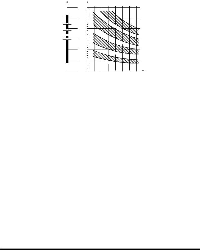
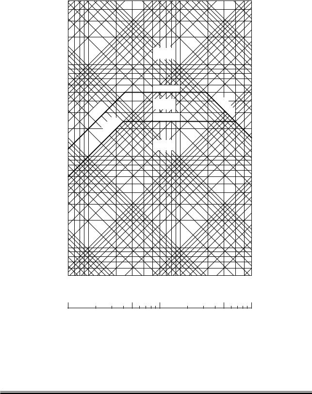
Fig. 17.02.01: Statistics of vertical hull vibrations in tankers and bulk carriers
Page of 2
178 06 92 4.1
The 2nd order moment acts only in the vertical direction. Precautions need only to be considered for 6-cylinder engines in general.
Resonance with the 2nd order moment may occur in the event of hull vibrations with more than 3 nodes. Contrary to the calculation of natural frequency with 2 and 3 nodes, the calculation of the 4 and 5-node natural frequencies for the hull is a rather comprehensive procedure and often not very accurate, despite advanced calculation methods.
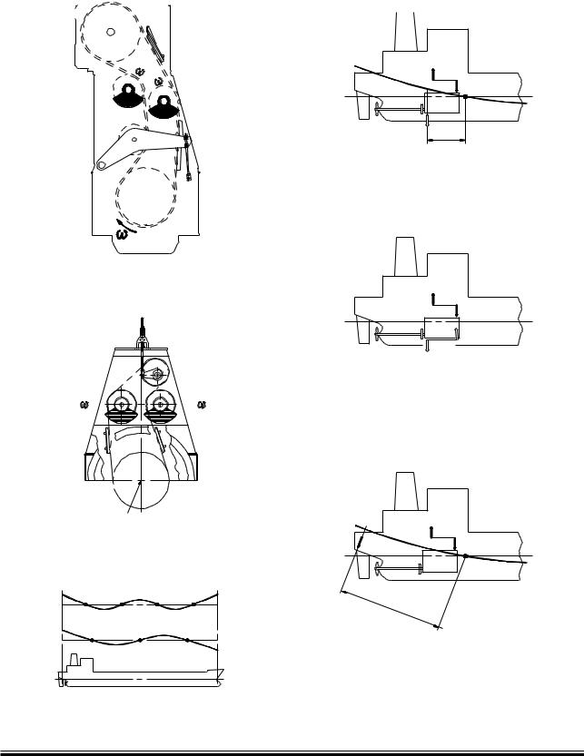
A 2nd order moment compensator comprises two counter rotating masses running at twice the engine speed. 2nd order moment compensators are not included in the basic extent of delivery.
Several solutions are available to cope with the 2nd order moment, as shown in Fig. 17.03.02, out of which the most cost efficient one can be chosen in the individual case, e.g.:
1)No compensators, if considered unnecessary on the basis of natural frequency, nodal point and size of the 2nd order moment.
2)A compensator mounted on the aft end of the engine, driven by chain, option: 4 31 233.
3)A compensator mounted on the fore end, driven from the crankshaft through a separate chain drive, option: 4 31 243.
As standard, the compensators reduce the external 2nd order moment to a level as for a 7-cylinder engine or less.
Briefly speaking, solution 1) is applicable if the node is located far from the engine, or the engine is positioned more or less between nodes. Solution 2) or 3) should be considered where one of the engine ends is positioned in a node or close to it, since a compensator is inefficient in a node or close to it and therefore superfluous.
MAN B&W K108ME C, K98ME/ME C, S90ME C, K90ME/ME C, S80ME C, K80/ME C
MAN Diesel |
198 42 19 8.3 |
|

MAN B&W |
17.02 |
|
|
|
Page of 2 |
A decision regarding the vibrational aspects and |
|
the possible use of compensators must be taken |
|
at the contract stage. If no experience is available |
|
from sister ships, which would be the best basis |
|
for deciding whether compensators are necessary |
|
or not, it is advisable to make calculations to de- |
|
termine which of the solutions should be applied. |
|
Preparation for compensators |
|
If compensator(s) are initially omitted, the en- |
|
gine can be delivered prepared for compensa- |
|
tors to be fitted on engine fore end later on, but |
|
the decision to prepare or not must be taken at |
|
the contract stage, options: 4 31 242. Measure- |
|
ments taken during the sea trial, or later in service |
|
and with fully loaded ship, will be able to show if |
|
compensator(s) have to be fitted at all. |
|
If no calculations are available at the contract |
|
stage, we advise to make preparations for the |
|
fitting of a compensator in the steering compart- |
|
ment. |
|
MAN B&W K108ME C, K98ME/ME C, S90ME C, K90ME/ME C, S80ME C, K80/ME C
MAN Diesel |
198 42 19 8.3 |
|
MAN B&W |
17.03 |
|
|
Electric Driven Moment Compensator
If it is decided not to use chain driven moment compensators and, furthermore, not to prepare the main engine for compensators to be fitted later, another solution can be used, if annoying vibrations should occur: An electrically driven moment compensator synchronised to the correct phase relative to the external force or moment can neutralise the excitation.
This type of compensator needs an extra seating fitted, preferably, in the steering gear room where vibratory deflections are largest and the effect of the compensator will therefore be greatest.
The electrically driven compensator will not give rise to distorting stresses in the hull, but it is more expensive than the engine-mounted compensators. It does, however, offer several advantages over the engine mounted solutions:
•When placed in the steering gear room, the compensator is not as sensitive to the positioning of the node as the compensators 2) and 3) mentioned in Section 17.02.
178 57 45-6.0
Page of 2
•The decision whether or not to install compensators can be taken at a much later stage of a project, since no special version of the engine structure has to be ordered for the installation.
•No preparation for a later installation nor an extra chain drive for the compensator on the fore end of the engine is required. This saves the cost of such preparation, often left unused.
•Compensators could be retrofit, even on ships in service, and also be applied to engines with a higher number of cylinders than is normally considered relevant, if found necessary.
•The compensator only needs to be active at speeds critical for the hull girder vibration. Thus, it may be activated or deactivated at specified speeds automatically or manually.
•Combinations with and without moment compensators are not required in torsional and axial vibration calculations, since the electrically driven moment compensator is not part of the mass-elastic system of the crankshaft.
Furthermore, by using the compensator as a vibration exciter a ship’s vibration pattern can easily be identified without having the engine running, e.g. on newbuildings at an advanced stage of construction. If it is verified that a ship does not need the compensator, it can be removed and reused on another ship.
It is a condition for the application of the rotating force moment compensator that no annoying longitudinal hull girder vibration modes are excited. Based on our present knowledge, and confirmed by actual vibration measurements onboard a ship, we do not expect such problems.
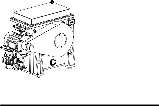
Fig. 17.03.01: MAN Diesel 1st or 2nd order electrically driven moment compensator, separately mounted, option: 4 31 605.
MAN B&W MC/MC-C/ME/ME-B/ME C/ME GI engines
MAN Diesel |
198 42 22 1.4 |
|
MAN B&W |
17.03 |
||||||
|
|
|
|
|
|
|
|
|
|
|
|
|
|
|
Page of 2 |
|
-OMENTæCOMPENSATOR |
#OMPENSATINGæMOMENT |
|||||
|
!FTæEND æOPTION æ æ æ |
& #æXæ,NODE |
|||||
|
|
|
|
|
OUTBALANCESæ- 6 |
||
|
|
|
|
|
|
|
|
|
|
|
|
|
|
|
|
|
|
|
|
|
|
|
|
|
|
|
|
|
|
|
|
|
- 6 |
|
|
|
.ODEæ!&4 |
|
|
& # |
,NODE |
-OMENTæFROMæCOMPENSATOR - #æREDUCESæ- 6
-OMENTæCOMPENSATOR |
- 6 |
&OREæEND æOPTION æ æ æ |
- # |
|
|
%LECTRICæDRIVENæMOMENTæCOMPENSATOR |
|
|
#OMPENSATINGæMOMENT &$æXæ,NODE OUTBALANCESæ- 6
#ENTREæLINE CRANKSHAFT
æANDæ çNODEæVERTICALæHULLæGIRDERæMODE
æ.ODE |
æ.ODE |
&$ |
- 6 |
.ODEæ!FT |
, |
NODE |
|
$ |
||
|
Fig. 17.03.02: Compensation of 2nd order vertical external moments |
178 27 10 4.1 |
|
MAN B&W MC/MC-C/ME/ME-B/ME C/ME GI engines
MAN Diesel |
198 42 22 1.3 |
|

MAN B&W |
17.04 |
|
|
|
Page of 1 |
Power Related Unbalance
To evaluate if there is a risk that 1st and 2nd order external moments will excite disturbing hull vibrations, the concept Power Related Unbalance (PRU) can be used as a guidance, see Table 17.04.01 below.
Based on service experience from a great number of large ships with engines of different types and cylinder numbers, the PRU values have been classified in four groups as follows:
PRU = External moment Nm/kW |
|
|
PRU Nm/kW |
Need for compensator |
|
|||||
|
|
0 |
- |
60 |
Not relevant |
|
|
|
||
Engine power |
|
|
|
60 |
- 120 |
Unlikely |
|
|
|
|
|
|
|
|
|
|
|
||||
With the PRU value, stating the external moment |
|
120 |
- 220 |
Likely |
|
|
|
|||
relative to the engine power, it is possible to give |
|
220 |
- |
|
Most likely |
|
|
|
||
an estimate of the risk of hull vibrations for a spe- |
|
|
|
|
|
|
|
|
||
cific engine. |
|
|
|
|
|
|
|
|
|
|
S90MC-C7/ME-C7 – 4,890 kW/cyl at 76 r/min |
|
|
|
|
|
|
|
|
||
|
5 cyl. |
6 cyl. |
7 cyl. |
8 cyl. |
9 cyl. |
10 cyl. |
11 cyl. |
12 cyl. |
14 cyl. |
|
PRU acc. to 1st order, Nm/kW |
N.a. |
0,0 |
24,7 |
2,1 |
29,7 |
N.a. |
N.a. |
N.a. |
N.a. |
|
PRU acc. to 2nd order, Nm/kW |
N.a. |
174,1 |
27,9 |
0,0 |
37,9 |
N.a. |
N.a. |
N.a. |
N.a. |
|
Based on external moments in layout point L1
N.a. Not applicable
Table 17.04.01: Power Related Unbalance (PRU) values in Nm/kW
Calculation of External Moments
In the table at the end of this chapter, the external moments (M1) are stated at the speed (n1) and MCR rating in point L1 of the layout diagram. For other speeds (nA), the corresponding external moments (MA) are calculated by means of the formula:
A 1 |
{n1 |
} |
|
|
M = M x |
nA |
|
2 |
|
|
|
kNm |
||
(The tolerance on the calculated values is 2.5%).
MAN B&W S90MC-C7/ME-C7
MAN Diesel |
198 46 76-2.2 |
|
MAN B&W |
17.05 |
|
|
Page of 3
Guide Force Moments
( TYPE |
8 TYPE |
|
|
|
|
4OPæBRACINGæLEVEL |
|
|
|
|
-IDDLEæPOSITIONæOFæGUIDEæPLANE |
,Z |
,Z |
|
$IST8 |
|
|
- ( |
|
#YL 8 |
- X |
, |
, |
|
||
|
|
|||
|
|
|
|
#RANKSHAFTæCENTREæLINE |
|
,X |
,X |
|
%NGINEæSEATINGæLEVEL |
|
|
|
||
|
: |
|
8 |
|
|
|
|
|
178 06 81 6.3 |
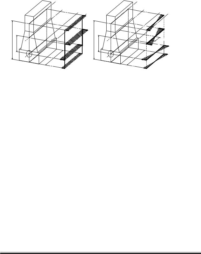
Fig. 17.05.01: H type and X type guide force moments
The so called guide force moments are caused by the transverse reaction forces acting on the crossheads due to the connecting rod/cranskahft mechanism. These moments may excite engine vibrations, moving the engine top athwartships and causing a rocking (excited by H moment) or twisting (excited by X moment) movement of the engine as illustrated in the above figure.
The guide force moments corresponding to the MCR rating (L1) are stated in Table 17.07.01.
Top bracing
The guide force moments are harmless except when resonance vibrations occur in the engine/ double bottom system.
As this system is very difficult to calculate with the necessary accuracy MAN Diesel strongly recommend, as standard, that top bracing is installed between the engine’s upper platform brackets and the casing side.
The vibration level on the engine when installed in the vessel must comply with MAN Diesel vibration units as stated in Fig. 17.05.02.
We recommend using the hydraulic top bracing which allow adjustment to the loading conditions of the ship. Mechanical top bracings with stiff connections are available on request.
With both types of top bracing above mentioned natural frequency will increase to a level where resonance will occur above the normal engine speed. Details of the top bracings are shown in Chapter 05.
Definition of Guide Force Moments
Over the years it has been discussed how to define the guide force moments. Especially now that complete FEM models are made to predict hull/ engine interaction, the propeller definition of these moments has become increasingly important.
H type Guide Force Moment (MH)
Each cylinder unit produces a force couple consisting of:
1.A force at crankshaft level.
2.Another force at crosshead guide level. The position of the force changes over one revolution as the guide shoe reciprocates on the guide.
MAN B&W MC/MC C, ME/ME-B/ME C/ME GI engines
MAN Diesel |
198 42 23 3.3 |
|
MAN B&W |
17.05 |
|
|
Page of 3
,IMITS¬VALID¬FOR¬SINGLE¬ORDER¬HARMONICS |
|
|
|
|
|
X æ æMM S |
|
|
æMM |
|
æMM |
|
|
|
|
|
|
|
|
|
))) |
|
æ |
|
|
|
|
|
|
|
|
|
|
æMMS |
|
|
|
|
|
|
|
ææ æ æMM S |
|
|
|
|
|
|
|
|
|
|
|
|
|
|
|
|
ç æMM |
|
|
|
|
|
æ |
|
|
|
¢ MM S |
|
$ISPLACEMENT |
|
|
|
)) |
¢ MS |
|
|
|
|
|
|
|
|
¢MM |
|
¢ MM S |
|
|
|
|
|
|
||
|
¢MM |
|
|
|
|
6ELOCITY |
|
|
) |
|
æ |
|
|
|
|
||
|
|
|
æMMS |
||
|
|
|
|
||
|
|
|
|
|
|
æMM S |
|
|
|
|
|
|
|
|
|
|
|
|
|
|
|
|
ç æMM |
|
|
|
|
|
æ |
|
|
|
|
|
!CCELERATION¬ |
|
|
|
|
|
æ |
|
|
|
|
|
|
|
|
|
|
|
æMMS |
æMM S |
|
|
|
|
|
|
|
|
|
|
|
|
|
|
|
|
ç æMM |
|
|
|
|
|
æ |
X æçæMM S |
|
|
|
|
|
|
|
æMMS |
|
æ |
æC MIN |
|
|
|
|
||
|
|
|
|
|
|
|
|
|
æMMS |
|
|
|
|
|
|
|
|
|
|
|
|
|
|
æ(Z |
|
|
æ(Z |
&REQUENCY |
æ(Z |
:ONEæ æ |
!CCEPTABLE |
|
|
|
|
:ONEæ æ |
6IBRATIONæWILLæNOTæDAMAGEæTHEæMAINæENGINE æHOWEVER |
|
|
||
æ |
UNDERæADVERSEæCONDITIONS æANNOYING HARMFULæVIBRATION |
|
|
||
æ |
RESPONSESæMAYæAPPEARæINæTHEæCONNECTEDæSTRUCTURES |
|
|
||
:ONEæ æ |
.OTæACCEPTABLE |
|
|
|
|
078 81 27-6.0
Fig.17.05.02: Vibration limits
MAN B&W MC/MC C, ME/ME-B/ME C/ME GI engines
MAN Diesel |
198 42 23 3.3 |
|

MAN B&W |
17.05 |
|
|
As the deflection shape for the H type is equal for each cylinder the Nth order H type guide force moment for an N cylinder engine with regular firing order is:
N x MH(one cylinder)
For modelling purposes the size of the forces in the force couple is:
Force = MH/L [kN]
where L is the distance between crankshaft level and the middle position of the crosshead guide (i.e. the length of the connecting rod.)
As the interaction between engine and hull is at the engine seating and the top bracing positions, this force couple may alternatively be applied in those positions with a vertical distance of (LZ).
Then the force can be calculated as:
ForceZ = MH/LZ [kN]
Any other vertical distance may be applied, so as to accomodate the actual hull (FEM) model.
The force couple may be distributed at any number of points in the longitudinal direction. A reasonable way of dividing the couple is by the number of top bracing and then applying the forces at those points.
ForceZ, one point = ForceZ, total/Ntop bracing, total [kN]
X type Guide Force Moment (MX)
The X type guide force moment is calculated based on the same force couple as described above. However as the deflection shape is twisting the engine each cylinder unit does not contribute with an equal amount. The centre units do not contribute very much whereas the units at each end contributes much.
A so called ‘Bi moment’ can be calculated (Fig. 17.05.01):
‘Bi moment’ = Σ[force couple(cyl.X) x distX] in kNm2
Page of 3
The X type guide force moment is then defined as:
MX = ‘Bi Moment’/L kNm
For modelling purpose the size of the four (4) forces can be calculated:
Force = MX/LX [kN]
where:
LX is the horizontal length between ‘force points’
Similar to the situation for the H type guide force moment, the forces may be applied in positions suitable for the FEM model of the hull. Thus the forces may be referred to another vertical level LZ above crankshaft centre line. These forces can be calculated as follows:
ForceZ, one point = MLxxxLL[kN]
In order to calculate the forces it is necessary to know the lengths of the connecting rods = L, which are:
Engine Type |
L in mm |
|
|
K108ME C6 |
3,400 |
|
|
K98ME6/7 |
3,220 |
|
|
K98ME C6/7 |
3,090 |
|
|
S90ME C7/8 |
3,270 |
|
|
K90ME9 |
3,320 |
|
|
K90ME-C9 |
3,120 |
|
|
K90ME C6 |
3,159 |
|
|
S80ME C9 |
3,450 |
|
|
S80ME C7/8 |
3,280 |
|
|
K80ME C9 |
2,975 |
|
|
K80ME C6 |
2,920 |
|
|
S70ME-C7/8 |
2,870 |
|
|
S70ME GI7/8 |
2,870 |
|
|
Engine Type |
L in mm |
|
|
L70ME C7/8 |
2,660 |
|
|
S65ME C8 |
2,730 |
|
|
S65ME GI8 |
2,730 |
|
|
S60ME C7/8 |
2,460 |
|
|
S60ME GI7/8 |
2,460 |
|
|
L60ME C7/8 |
2,280 |
|
|
S50ME C7/8 |
2,050 |
|
|
S50ME-B9 |
2,114 |
|
|
S50ME-B8 |
2,050 |
|
|
S40ME-B9 |
1,770 |
|
|
S35ME-B9 |
1,550 |
|
|
MAN B&W ME/ME-B/ME C/ME GI engines
MAN Diesel |
198 45 17 0.5 |
|

MAN B&W |
17.06 |
|
|
|
Page of 2 |
Axial Vibrations
When the crank throw is loaded by the gas pressure through the connecting rod mechanism, the arms of the crank throw deflect in the axial direction of the crankshaft, exciting axial vibrations. Through the thrust bearing, the system is connected to the ship’s hull.
Generally, only zero node axial vibrations are of interest. Thus the effect of the additional bending stresses in the crankshaft and possible vibrations of the ship`s structure due to the reaction force in the thrust bearing are to be considered.
An axial damper is fitted as standard on all engines, minimising the effects of the axial vibrations (4 31 111).
Torsional Vibrations
The reciprocating and rotating masses of the engine including the crankshaft, the thrust shaft, the intermediate shaft(s), the propeller shaft and the propeller are for calculation purposes considered as a system of rotating masses (inertias) interconnected by torsional springs. The gas pressure of the engine acts through the connecting rod mechanism with a varying torque on each crank throw, exciting torsional vibration in the system with different frequencies.
In general, only torsional vibrations with one and two nodes need to be considered. The main critical order, causing the largest extra stresses in the shaft line, is normally the vibration with order equal to the number of cylinders, i.e., six cycles per revolution on a six cylinder engine. This resonance is positioned at the engine speed corresponding to the natural torsional frequency divided by the number of cylinders.
The torsional vibration conditions may, for certain installations require a torsional vibration damper, option: 4 31 105.
Based on our statistics, this need may arise for the following types of installation:
•Plants with controllable pitch propeller
•Plants with unusual shafting layout and for special owner/yard requirements
•Plants with 8 cylinder engines.
The so called QPT (Quick Passage of a barred speed range Technique), is an alternative to a torsional vibration damper, on a plant equipped with a controllable pitch propeller. The QPT could be implemented in the governor in order to limit the vibratory stresses during the passage of the barred speed range.
The application of the QPT, option: 4 31 108, has to be decided by the engine maker and MAN Diesel based on final torsional vibration calculations.
Six cylinder engines, require special attention. On account of the heavy excitation, the natural frequency of the system with one-node vibration should be situated away from the normal operating speed range, to avoid its effect. This can be achieved by changing the masses and/or the stiffness of the system so as to give a much higher, or much lower, natural frequency, called undercritical or overcritical running, respectively.
Owing to the very large variety of possible shafting arrangements that may be used in combination with a specific engine, only detailed torsional vibration calculations of the specific plant can determine whether or not a torsional vibration damper is necessary.
Undercritical running
The natural frequency of the one-node vibration is so adjusted that resonance with the main critical order occurs about 35 45% above the engine speed at specified MCR.
Such undercritical conditions can be realised by choosing a rigid shaft system, leading to a relatively high natural frequency.
The characteristics of an undercritical system are normally:
•Relatively short shafting system
•Probably no tuning wheel
•Turning wheel with relatively low inertia
•Large diameters of shafting, enabling the use of shafting material with a moderate ultimate tensile strength, but requiring careful shaft alignment, (due to relatively high bending stiffness)
•Without barred speed range
MAN B&W S90MC-C/ME C, S80MC-C/ME C, S70MC/MC-C/ME C/ME GI, L70MC-C/ME C, S65ME C/ME GI, S60MC/MC-C/ME C/ME GI, L60MC-C/ ME C, S50MC/MC C/ME-B/ME-C, S46MC-C, S42MC, S40ME-B, S35MC/ ME-B, L35MC, S26MC
MAN Diesel |
198 42 25 7.4 |
|