

line con 0
password 7 04750E12182E5E45001702
!
line vty 0 4
password 7 122A00140719051033
!
Warning Password encryption does not provide a very high level of security. There are widely available passwords crackers that can reverse the encryption. I do, however, recommend using the password encryption command on all routers. I also recommend that you take additional security measures to protect your passwords.
Configuring Banner Messages
As mentioned in the section "In Brief" at the beginning of this chapter, you can display banner messages to users who are attempting to gain access to the router. There are four types of banner messages:
∙Message of the Day (MOTD)—Displayed at login. Useful for sending messages that affect all network users.
∙Login—Displayed after the Message of the Day banner appears and before the login prompts.
∙EXEC—Displayed whenever an EXEC process is initiated.
∙Incoming—Displayed on terminals connected to reverse Telnet lines.
The process for configuring banner messages is fairly simple. Enter the following command in global configuration mode:
banner {exec|motd|login|incoming} [delimited character] – <message> [delimited character]
Here is a sample MOTD banner:
SecureRouter#config t
Enter configuration commands, one per line. End with CNTL/Z.
SecureRouter(config)#banner motd #
Enter TEXT message. End with the character '#'.
*******************************************************
* |
WARNING...WARNING...WARNING...WARNING |
* |
|
* |
YOU HAVE ACCESSED A RESTRICTED DEVICE |
* |
|
* |
USE OF THIS DEVICE WITHOUT |
PRIOR AUTHORIZATION |
* |
* |
OR FOR PURPOSES WHICH AUTHORIZATION HAS NOT BEEN |
* |
|
* |
GRANTED IS STRICTLY |
PROHIBITED!!! |
* |
*******************************************************
#
SecureRouter(config)#end
SecureRouter#
22
The results of setting the MOTD banner message can be seen by using the show running−config command or by logging into the router. The following is an example of logging into the router from the console port:
SecureRouter con0 is now available
......
Press RETURN to get started.
......
*******************************************************
* |
WARNING...WARNING...WARNING...WARNING |
* |
|
* |
YOU HAVE ACCESSED A RESTRICTED DEVICE |
* |
|
* |
USE OF THIS DEVICE WITHOUT |
PRIOR AUTHORIZATION |
* |
* |
OR FOR PURPOSES WHICH AUTHORIZATION HAS NOT BEEN |
* |
|
* |
GRANTED IS STRICTLY |
PROHIBITED!!! |
* |
*******************************************************
SecureRouter>
EXEC banner messages, as mentioned earlier, are invoked when a user attempts to gain access into privileged mode. (Accessing privileged mode was explained in "Configuring Enable Mode Security" earlier in this chapter.) Industry−standard best practices recommend configuring a MOTD banner message as well as an EXEC banner message. Working still on the same router, here's how to configure an EXEC banner to complement the MOTD banner. This can be accomplished using the following configuration:
SecureRouter#config t
Enter configuration commands, one per line. End with CNTL/Z. SecureRouter(config)#banner exec #
Enter TEXT message. End with the character '#'.
*******************************************************
* |
WARNING...WARNING...WARNING...WARNING |
* |
* |
|
* |
* |
THIS IS A REMINDER...THIS IS A REMINDER |
* |
* |
|
* |
* |
YOU HAVE ACCESSED A RESTRICTED DEVICE |
* |
* |
USE OF THIS DEVICE WITHOUT PRIOR AUTHORIZATION |
* |
* |
OR FOR PURPOSES WHICH AUTHORIZATION HAS NOT BEEN |
* |
* |
GRANTED IS STRICTLY PROHIBITED!!! |
* |
*******************************************************
#
SecureRouter(config)#end
SecureRouter#
The results of setting the EXEC message can be seen by using the show running−config command or by using the telnet command to remotely connect to a router with the EXEC banner enabled. The results of configuring both the MOTD banner and the EXEC banner can be seen here:
R1#telnet 192.168.10.1
Trying 192.168.10.1 ... Open
*******************************************************
* |
WARNING...WARNING...WARNING...WARNING |
* |
|
* |
YOU HAVE ACCESSED A RESTRICTED DEVICE |
* |
|
* |
USE OF THIS DEVICE WITHOUT |
PRIOR AUTHORIZATION |
* |
* |
OR FOR PURPOSES WHICH AUTHORIZATION HAS NOT BEEN |
* |
|
* |
GRANTED IS STRICTLY |
PROHIBITED!!! |
* |
23
*******************************************************
User Access Verification
Username: Fred Password:
*******************************************************
* |
WARNING...WARNING...WARNING...WARNING |
* |
* |
|
* |
* |
THIS IS A REMINDER...THIS IS A REMINDER |
* |
* |
|
* |
* |
YOU HAVE ACCESSED A RESTRICTED DEVICE |
* |
* |
USE OF THIS DEVICE WITHOUT PRIOR AUTHORIZATION |
* |
* |
OR FOR PURPOSES WHICH AUTHORIZATION HAS NOT BEEN |
* |
* |
GRANTED IS STRICTLY PROHIBITED!!! |
* |
*******************************************************
SecureRouter>en
Password:
SecureRouter#
Notice that the EXEC banner is displayed after the user has passed the local authentication phase on the router.
Configuring SNMP Security
There is no specific command that you use to enable SNMP. To configure SNMP support, perform the tasks described in the following steps, only the first two steps are mandatory:
1.Enable the SNMP community string to define the relationship between the network management station and the agent with the following command:
snmp−server community <string> {ro|rw} {number}
The number value references an optional access−list.
2. Use this command to configure the router to send traps to an NMS host:
snmp−server host host [version {1|2c}] <community string> <notification type>
3.Configure the type of traps for which a notification is sent to the NMS. You do so with the following command:
snmp−server enable traps [notification type] – [notification option]
4.Set the system contact, location, and serial number. You can set the systems contact with the snmp−server contact [text] command. You set the location with the snmp−server location [text] command, and you set the serial number with the snmp−server chassis−id [text] command.
5.Use the access−list command to specify a list of hosts that are allowed read−, read/write, or write−only access to the router.
Figure 1.2 shows Router A, which is configured to allow SNMP read−only access and read/write access from two separate hosts. Router A is also configured to send SNMP trap information to the same two hosts. The following lines show how Router A should be configured so SNMP access
24
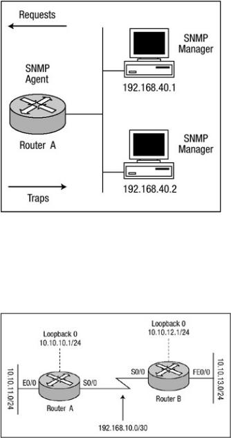
from both host 192.168.40.1 and 192.168.40.2 is allowed and SNMP trap information is sent to both hosts:
access−list 12 permit 192.168.40.1 access−list 13 permit 192.168.40.2 snmp−server contact Harris
snmp−server location Network Engineering snmp−server chassis−id 100000333 snmp−server community observe RO 12 snmp−server community adjust RW 13 snmp−server host 192.168.40.1 observe snmp snmp−server host 192.168.40.2 adjust snmp
Figure 1.2: Router A configured for SNMP.
Configuring RIP Authentication
There are two versions of Routing Information Protocol (RIP): version 1 and version 2. RIP version 1 does not support authentication of routing updates; however, RIP version 2 supports both plain text and MD5 authentication. Figure 1.3 shows two routers, Router A and Router B, that exchange RIP version 2 MD5 authentication updates.
Figure 1.3: Router A and Router B configured for RIP authentication.
Configuring authentication of RIP version 2 updates is fairly easy and very uniform. The basic configuration includes the following steps:
25

1.Define the key chain using the command key−chain < name> in global configuration mode. This command transfers you to the key chain configuration mode.
2.Specify the key number with the key < number> command in key chain configuration mode. You can configure multiple keys.
3.For each key, identify the key string with the key−string < string> command.
4.Configure the period for which the key can be sent and received. Use the following commands:
accept−lifetime <starttime> {infinite|end−time|duration − seconds}
send−lifetime <starttime> {infinite|end−time|duration seconds}
5.Exit key chain configuration mode with the exit command.
6.Under interface configuration mode, enable the authentication of RIP updates with this command:
ip rip authentication key−chain <key chain name>
This command is all that is needed to use plain text authentication.
7.Optionally, under interface configuration mode, enable MD5 authentication of RIP updates using the ip rip authentication mode md5 command.
The listings that follow show how Router A and Router B in Figure 1.3 should be configured to authenticate updates from one another using RIP MD5 authentication. Listing 1.1 shows the configuration of Router A, and Listing 1.2 shows the configuration of Router B.
Listing 1.1: Router A's configuration with MD5 authentication.
key chain systems key 1
key−string router
!
interface Loopback0
ip address 10.10.10.1 255.255.255.0
!
interface Ethernet0/0
ip address 10.10.11.1 255.255.255.0
!
interface Serial0/0
ip address 192.168.10.1 255.255.255.252 ip rip authentication mode md5
ip rip authentication key−chain systems clockrate 64000
!
router rip version 2 network 10.0.0.0
network 192.168.10.0 no auto−summary
Listing 1.2: Router B's configuration with MD5 authentication.
key chain cisco key 1
key−string router
!
interface Loopback0
ip address 10.10.12.1 255.255.255.0
!
26