


FastEthernet0 is up, line protocol is up
Internet address is 192.168.10.1/24
Broadcast address is 255.255.255.255
Address determined by non−volatile memory
MTU is 1500 bytes
Helper address is not set
Directed broadcast forwarding is disabled
Outgoing access list is not set
Inbound access list is permit−40
Proxy ARP is enabled
Configuring Commented Access Lists
When you use named access lists, you are able to provide a small description of the access list within the name, as shown in Listing 7.15 and Listing 7.16. Sometimes, though, the name of an access list does not provide enough information about what the access list does or what function each line within the access list provides. In 12.0.2 code, Cisco released a feature known as commented access lists. In Listings 7.1 and Listing 7.15, Raul has an access list configured that permits the 192.168.20.0 network and denies all others. In Listing 7.15, a name was used to define the access list instead of a number; I attempted to give the access list a name that was relevant to the function that it provided. In Listing 7.1, a standard numbered access list was used to define the same access lists; however, no descriptive information about the access list could be made with the numbered access list. You can add a comment to standard and extended access lists as well as to numbered and named access lists. Follow these steps to configure comments within a name−based access list:
1. Use the following configuration command to define a named access list:
ip access−list <standard | extended> name
2.Use the remark command to define the comment on an access list basis or on a per−filter−rule basis. The remark parameter is limited to 100 characters, including spaces.
3.Use this command to select the input interface under which the access list will be applied:
interface <interface name> <interface number>
4.Use the following command to bind the access list to the interface and to apply the filter to packets entering into or exiting the interface:
ip access−group name {in | out}
Follow these steps to configure comments within a numbered access:
1.Use the following configuration command to define the numbered access list and to define the comment on an access list basis:
access−list access−list−number remark remark
2. Use this command to select the input interface under which the access list will be applied:
interface <interface name> <interface number>
3.Use this command to bind the access list to the interface and to apply the filter to packets entering into or exiting the interface:
ip access−group access list number {in | out}
252
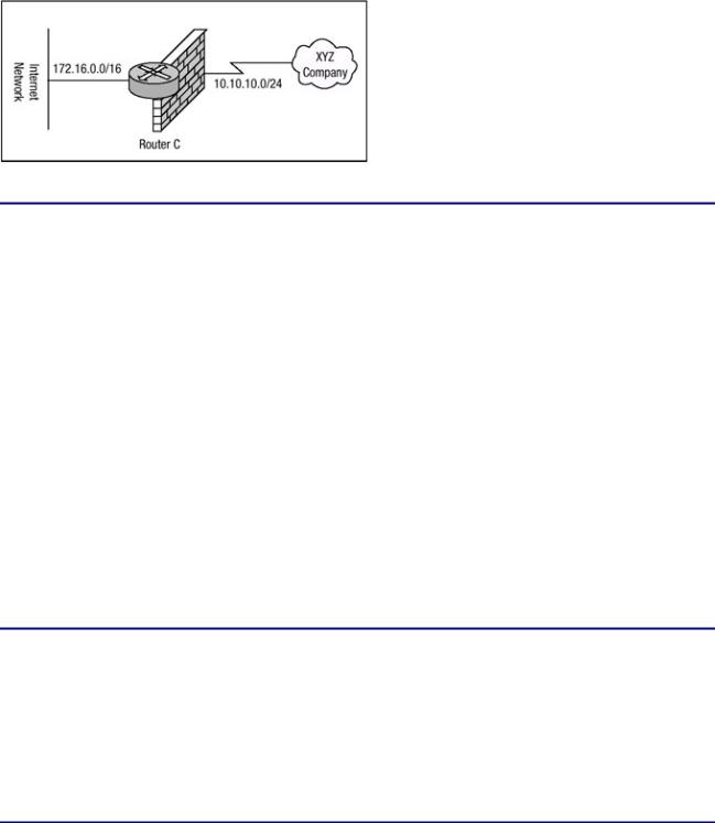
Figure 7.7 displays a router with two networks directly attached to it. The router, Router C, has a large access list configuration defined, and if remarks weren't used, the access list would be fairly complicated to fully understand. To add clarity to the access list, remarks have been defined within the list. Router C will be configured with a name−based access list and the appropriate remarks will be added within the access list. Listing 7.18 displays the configuration of Router C.
Figure 7.7: Router C permitting and denying traffic.
Listing 7.18: Commented named access list on Router C.
hostname Router−C
!
interface FastEthernet0/0
ip address 172.16.15.1 255.255.255.0 no ip directed−broadcast
!
interface Serial1/0
ip address 10.10.10.1 255.255.255.0 ip access−group Commented in
no ip directed−broadcast
!
ip access−list extended Commented
remark Deny any inbound request unless initiated from inside permit tcp any 172.16.0.0 0.0.255.255 established
remark Permit mail traffic to this host permit tcp any host 172.16.15.83 eq smtp
remark Permit telnet from XYZ company to our company permit tcp 10.10.10.0 0.0.0.255 172.16.0.0 0.0.255.255 −
eq telnet
remark Permit FTP from XYZ company to our company
permit tcp 10.10.10.0 0.0.0.255 172.16.0.0 0.0.255.255 eq ftp remark Allow DNS traffic to the internal DNS server
permit udp any host 172.16.15.84 eq domain remark Deny all other traffic
deny ip any any
Router C has been configured with an extended name−based access list. Within the access list remarks provide clarity on the function of each filter rule statement. As mentioned earlier, comments can also be listed for numbered access lists. Using the same requirements that were listed with Listing 7.18, Router C can now be configured with a numbered access list that contains remarks for each filter rule. An extended numbered access list is used to accomplish the same thing Listing 7.18 accomplishes. Listing 7.19 displays the configuration of Router C using numbered access lists.
Listing 7.19: Commented numbered access list on Router C.
hostname Router−C
!
interface FastEthernet0/0
ip address 172.16.15.1 255.255.255.0 no ip directed−broadcast
253

!
interface Serial1/0
ip address 10.10.10.1 255.255.255.0
ip access−group |
121 in |
no ip directed−broadcast |
|
! |
|
access−list 121 |
remark Deny any inbound request |
access−list 121 |
permit tcp any 172.16.0.0 0.0.255.255 − |
established |
|
access−list 121 |
remark Permit mail traffic to this host |
access−list 121 |
permit tcp any host 172.16.15.83 eq smtp |
access−list 121 |
remark Permit telnet from XYZ company |
access−list 121 |
permit tcp 10.10.10.0 0.0.0.255 − |
172.16.0.0 0.0.255.255 eq telnet |
|
access−list 121 |
remark Permit FTP from XYZ company to our − |
company |
|
access−list 121 |
permit tcp 10.10.10.0 0.0.0.255 − |
172.16.0.0 0.0.255.255 eq ftp |
|
access−list 121 |
Allow DNS traffic to the internal DNS server |
access−list 121 |
permit udp any host 172.16.15.84 eq domain |
access−list 121 |
remark Deny all other traffic |
access−list 121 |
deny ip any any |
|
|
Note Because of the format limitations of this book, some lines of code listed above have been broken with a hyphen.
Configuring Dynamic Access Lists
Dynamic access lists permit or deny traffic based on user credentials that are passed to the Lock and Key router for user authentication. To be permitted access to a host behind a router configured for Lock and Key security, a user must first telnet to the router and pass an authentication phase. If authentication is successful, a temporary access list is created; it will enable the user to connect to the intended destination. To configure a router to provide Lock and Key security services for hosts, follow these steps:
1. Use the following global configuration command to define a dynamic access list:
access−list <access−list−number> <dynamic dynamic−name> − <timeout minutes> <deny | permit> telnet <source − source−wildcard> <destination destination−wildcard> − <precedence precedence> <tos tos> <established> <log> −
2.Optionally, use the access−list dynamic−extend command to extend the absolute timer of the dynamic ACL by six minutes when another Telnet session is opened into the router.
3.Use this command to configure user authentication:
username name password secret
4.Use the following command to select the input interface under which the access list will be applied:
interface <interface name> <interface number>
5.Use the following command to bind the access list to the interface and to apply the dynamic filter to packets entering into the interface:
ip access−group name <in>
6. Use this command to define one or more virtual terminal (vty) ports:
line vty <line−number> <ending−line−number>
254
7.Use the login local command to specify that user authentication should use the locally configured security database.
8.Use the following command in line configuration mode to enable the creation of temporary access list entries:
autocommand access−enable host [timeout minutes]
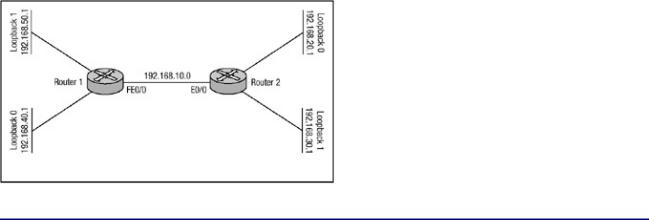
The network displayed in Figure 7.8 will demonstrate dynamic access list security. Router 1 and Router 2 are each configured with two loopback interfaces. When Router 2 attempts to connect to one of the loopback interfaces on Router 1, it must first telnet to Router 1 and will be asked to authenticate via the local security database. If authentication takes place correctly, Router 2 will be disconnected from Router 1 and then will be allowed to communicate with the host on the loopback interface. The configuration of Router 1 is shown in Listing 7.20, and the configuration of Router 2 is shown in Listing 7.21.
Figure 7.8: Dynamic access list security.
Listing 7.20: Configuration of Router 1 for dynamic access lists.
hostname Router−1
!
username R2 password 0 R2
!
interface Loopback0
ip address 192.168.40.1 255.255.255.0 no ip directed−broadcast
!
interface Loopback1
ip address 192.168.50.1 255.255.255.0 no ip directed−broadcast
!
interface FastEthernet0/0
ip address 192.168.10.2 255.255.255.0 ip access−group 101 in
no ip directed−broadcast
!
ip classless
ip route 192.168.20.0 255.255.255.0 192.168.10.1 ip route 192.168.30.0 255.255.255.0 192.168.10.1 no ip http server
!
access−list 101 permit tcp any host 192.168.10.2 eq telnet access−list 101 dynamic PermitR2 permit tcp −
host 192.168.20.1 host 192.168.40.1 access−list 101 dynamic PermitR2 permit tcp −
host 192.168.20.1 host 192.168.50.1
!
line con 0 session−timeout 30
255

exec−timeout 30 0 login local transport input none line aux 0
line vty 0 4 session−timeout 30 exec−timeout 30 0 login local
autocommand access−enable timeout 5
!
Listing 7.21: Configuration of Router 2 for dynamic access lists.
hostname Router−2
!
username R1 password 0 R1
ip telnet source−interface Loopback1
!
interface Loopback1
ip address 192.168.20.1 255.255.255.0 no ip directed−broadcast
!
interface Loopback2
ip address 192.168.30.1 255.255.255.0 no ip directed−broadcast
!
interface Ethernet0/0
ip address 192.168.10.1 255.255.255.0 no ip directed−broadcast
!
ip classless
ip route 192.168.40.0 255.255.255.0 192.168.10.2 ip route 192.168.50.0 255.255.255.0 192.168.10.2
!
line con 0 session−timeout 30 exec−timeout 30 0 login local transport input none line aux 0
line vty 0 4 session−timeout 30 exec−timeout 30 0 login local
!
Note Because of the format limitations of this book, some lines of code listed above have been broken with a hyphen.
As you can probably tell, there is nothing special about Router 2's configuration. It is Router 1's configuration that matters. The only special command configured on Router 2 is the IP telnet source−interface command, which is used to have Router 2 source the Telnet packet from the specified loopback interface because, by default, the router will source the packet with the output interface's IP address as the source of the packet.
You can first try to establish a Telnet connection to the 192.168.40.1 loopback interface of Router 1 from Router 2 to verify that the access list is not allowing access. The following code displays the output of a Telnet connection request from Router 2 to the loopback interface of Router 1. To verify that the access list is denying access, Router 1 is configured to debug packets using the debug IP
256
packet detail command and is configured to log all events to the internal buffer using the logging buffered command.
Router−2#telnet 192.168.40.1 Trying 192.168.40.1 ...
% Destination unreachable; gateway or host down
Router−2#
As you can see, Router 1 has denied Router 2 access to the 192.168.40.1 interface. Looking back at the log information on Router 1 will in fact show that the packet request was made for access to 192.168.40.1 but was denied. The following output can be seen by issuing the show logging command on Router 1:
Router−1#show logging
Syslog logging: enabled(1 messages dropped, 0 flushes, − 0 overruns)
Console logging: level debugging, 81 messages logged Monitor logging: level debugging, 0 messages logged Buffer logging: level debugging, 9 messages logged
Trap logging: level informational, 24 message lines logged Log Buffer (2000000 bytes):
IP: s=192.168.20.1, d=192.168.40.1, len 44, access denied TCP src=11007, dst=23, seq=3683728902, ack=0, win=4128 SYN ip: s=192.168.10.2, d=192.168.20.1, len 56, sending
ICMP type=3, code=13 Router−1#
Router 1 has in fact denied the connection request. Now I'll go back to Router 2 and attempt a Telnet connection to the 192.168.10.2, Fast Ethernet0/0 interface of Router 1. The Telnet connection request from Router 2 to Router 1 can be seen in the following output. Router 1 is still configured with the debug IP packet detail command so that the connection request can be verified:
Router−2#telnet 192.168.10.2
Trying 192.168.10.2 ... Open
User Access Verification
Username: R2
Password: R2
[Connection to 192.168.10.2 closed by foreign host] Router−2#
After Router 2 makes the connection request to Router 1 and is authenticated via the local security database, Router 1 disconnects the Telnet session with Router 2 and creates the temporary access list entries in access list 101, permitting traffic from 192.168.20.1 to 192.168.40.1. The output in Listing 7.22 displays the creation of the temporary access lists on Router 1. To display the information, issue the show IP access−lists command.
Listing 7.22: Temporary access list entries on Router 1.
Router−1#show ip access−lists Extended ip access list 101
permit tcp any host 192.168.10.2 eq telnet log (38 matches) Dynamic PermitR2 permit tcp host 192.168.20.1 host 192.168.40.1 −
log
permit tcp host 192.168.20.1 host 192.168.40.1 log −
257

(time left 293)
Dynamic PermitR2 permit tcp host 192.168.20.1 host 192.168.50.1 − log
permit tcp host 192.168.20.1 host 192.168.40.1 log − (time left 293)
Router−1#
It should also be helpful to take a look at the logging information. The output in Listing 7.23 displays the output from the show logging command.
Listing 7.23: Show logging on Router 1.
Router−1#show logging
Syslog log: enabled (1 messages dropped, 0 flushes, 0 overruns)
Console logging: level debugging, 679 messages logged
Monitor logging: level debugging, 0 messages logged
Buffer logging: level debugging, 607 messages logged
Trap logging: level informational, 27 message lines logged
Log Buffer (2000000 bytes):
%SEC−6−IPACCESSLOGP: list 101 permitted tcp 192.168.20.1 − (11010) −> 192.168.10.2(23), 1 packet
ip: s=192.168.20.1, d=192.168.10.2, len 44, rcvd 3
TCP src=11010, dst=23, seq=1082833484, ack=0, win=4128 SYN ip: s=192.168.10.2, d=192.168.20.1, len 44, sending
TCP src=23,dst=11010,seq=2196401629,ack=1082833485,win=4128 ACK SYN
ip: s=192.168.20.1, d=192.168.10.2, len 40, rcvd 3
TCP src=11010,dst=23,seq=1082833485,ack=2196401630,win=4128 ACK ip: s=192.168.20.1, d=192.168.10.2, len 52, rcvd 3
TCP src=11010, dst=23, seq=1082833485, ack=2196401630, win=4128 ACK PSH
At this point, I have been authenticated and Router 1 has created the temporary access list entries to allow connectivity to Router 2. I should now be able to connect to the loopback interface of Router 1 because the temporary access list entry has been created to allow for the connectivity from 192.168.20.1 to 192.168.40.1. The following output details the connection request to Router 1's loopback interface:
Router−2#telnet 192.168.40.1
Trying 192.168.40.1 ... Open
User Access Verification
Username: R2
Password:
Router−1#
After the connection request is made to Router 1, you can look again at the access list configuration and see that packets have matched the temporary access lists. The following output displays the information from the show IP access−lists command:
Router−1#show ip access−lists Extended ip access list 101
permit tcp any host 192.168.10.2 eq telnet (40 matches)
Dynamic PermitR2 permit tcp host 192.168.20.1 host 192.168.40.1 permit tcp host 192.168.20.1 host 192.168.40.1 (38 matches) −
258

(time left 275)
Dynamic PermitR2 permit tcp host 192.168.20.1 host 192.168.50.1 permit tcp host 192.168.20.1 host 192.168.40.1 (38 matches) −
(time left 275) Router−1#
Note Because of the format limitations of this book, some lines of code listed above have been broken with a hyphen.
Of particular note in the preceding output is the time left 275 field; this field displays the amount of idle time remaining before the timeout period is reached and the router tears down the temporary access list entry. In Listing 7.20, the timeout period was configured to three minutes using the autocommand access−enable command. This configured all dynamic access lists' idle timeout period to five minutes. If the idle timeout value is reached and the dynamic entry is deleted, any user that authenticated to Router 1 using the username R2 will have to reauthenticate before gaining access again. Sometimes security administrators need a finer granularity of control on a per−user basis. One user may need to have a longer idle timeout value than another user; however, with the preceding configuration, all users have the same idle timeout value. Router 1's configuration in Listing 7.20 can be altered to provide different timeout values on the basis of local database users. Listing 7.24 displays Router 1's new configuration, which has defined multiple local security database entries and configured a specific idle timeout value for each local database entry.
Listing 7.24: New configuration of Router 1.
hostname Router−1
!
username R2 password 0 R2
uername R2 autocommand access−enable timeout 3 username Cisco password 0 Cisco
username Cisco autocommand access−enable timeout 5 username Systems password 0 Systems
username Systems autocommand access−enable timeout 7
!
interface Loopback0
ip address 192.168.40.1 255.255.255.0 no ip directed−broadcast
!
interface Loopback1
ip address 192.168.50.1 255.255.255.0 no ip directed−broadcast
!
interface FastEthernet0/0
ip address 192.168.10.2 255.255.255.0 ip access−group 101 in
no ip directed−broadcast
!
ip classless ip route 192.168.20.0 255.255.255.0 192.168.10.1
ip route 192.168.30.0 255.255.255.0 192.168.10.1 no ip http server
!
access−list 101 permit tcp any host 192.168.10.2 eq telnet log access−list 101 dynamic PermitR2 permit tcp −
host 192.168.20.1 host 192.168.40.1 log access−list 101 dynamic PermitR2 permit tcp − host 192.168.20.1 host 192.168.50.1 log
!
line con 0 session−timeout 30 exec−timeout 30 0 login local transport input none
259