

26 Chapter 2 – Schematic Capture Editor
Adding Connections
Connections are added to the Schematic design to make connectivity between electrical pins. When translated to the PCB design, these connections give you your net list.
You can add connections in a number of ways:
Using the Add Connection option from the Add menu or from the Schematic Toolbar, click on the pin to start adding a connection, or;
Double-clicking on a component pin to start a new connection, or;
'Dragging' off an unconnected component pin to start a new connection.
For this tutorial we will use the ‘dragging off pins’ method as this is the easiest to start with.
To add connections by dragging off pins
To aid the addition of connections to a schematic, you can simply ‘drag’ off an electrical pin, each click of the mouse will then add a corner. Moving over another electrical pin will allow you to finish the connection.
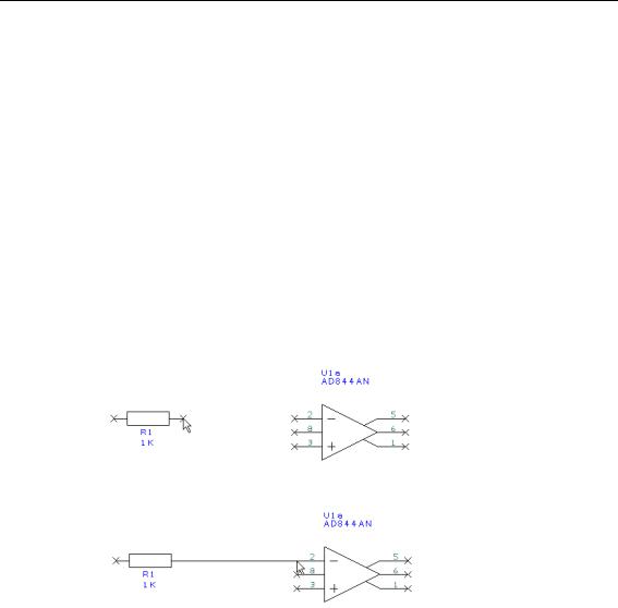
Using the design that you have created so far, zoom in on the area around R1 like the picture below.
Click and drag (keeping the mouse button pressed down) off pin 2 of R1, this will start a new connection. Move the mouse over U1a pin 2 and single click to finish.
You do not have to be exactly over a pin to finish a connection; as long as the cursor is within range then it will snap onto the terminal.
Click the mouse button once to finish. You’ll notice that the component pin terminals X disappear when you connect to it; this indicates that it is connected.
To join connections together
There are a couple of connections which must be connected together. Let’s assume that you’ve made a connection and now you need to connect another to it using a junction dot. When you attempt to finish a connection on an existing connection, when you release the mouse, the connection will automatically be added (as if it were an electrical terminal) and a junction dot displayed to indicate it is connected.
Following our sketched design above, complete the design adding the connections required.