


14 Chapter 2 – Schematic Capture Editor
Click the OK button to start a new Schematic design.
Note: If you intend creating a PCB without a Schematic design (which you can do), just click the New PCB Design button and OK. Then skip to the chapter headed, Starting a New PCB Design.
Your PCB Artist window will look like this ready to start:
For now, we will progress on to adding components to the design.
Adding Components
To add a Component
There are two methods for adding components; we will use the Interaction bar to start with, you can also use the Add Component option as well.
The Interaction bar has automatically been started when creating a new Schematic design. If it hasn’t, click the <F9> shortcut key to display it.
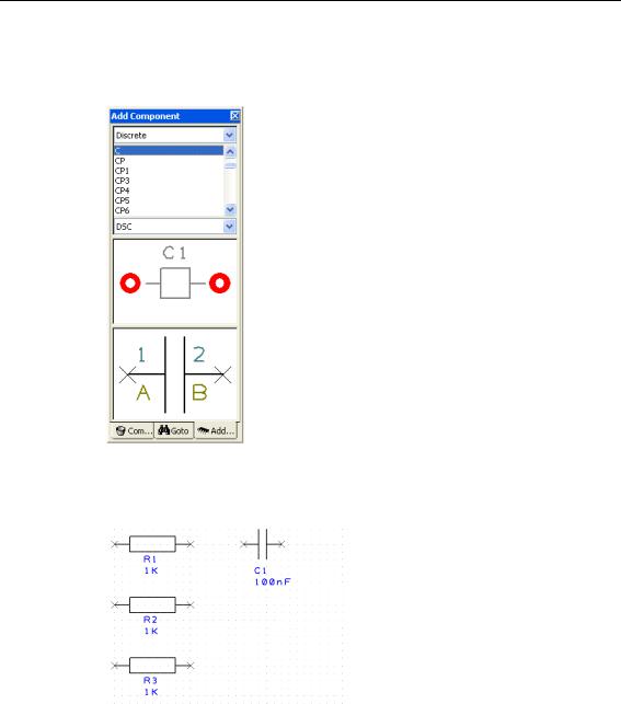
Select the Add Component browser tab at the bottom of the Interaction bar.

Chapter 2 – Schematic Capture Editor 15
From the list of available libraries, select the Discrete library. Click on the small down arrow to reveal the drop down list and then make the selection.

16 Chapter 2 – Schematic Capture Editor
The Component list will be populated with components. Selecting this library will automatically select the first component in the list as well.
Scroll down the list of components using the vertical scroll bar. The first in the list is the generic ‘C’ component. You can also click in this list and type the first and subsequent letters and numbers of the item required.
Scroll down and select the component R. This is a generic resistor that we will change the Value for later on. You can also work with specific named parts if you prefer, both methods are acceptable in PCB Artist.

Chapter 2 – Schematic Capture Editor 17
A preview of both the Schematic and PCB symbols will be displayed (the PCB symbol is top most in the preview).
Once you have the correct component, you can add it by selecting the symbol preview and dragging it into the design. You can also add the component by selecting and dragging its name.
This is a one-shot process. If you wish to add more of the same type, drag another from the bin.
The component is currently on the end of your cursor. To place it in the design, click the left mouse button once.
You need 3 resistors in total for the final circuit. Once the first one has been placed, pick and drag 2 more from the Component Browser window. Position then in a stack like the picture below:
To pan & zoom in the design
To view the resistors closer, roll the mouse wheel button forward to zoom in. If you zoom in too fast (and too far), roll the mouse wheel button backwards (slowly). If you zoom too far either way, press <A> on the keyboard to View All and then zoom in or out again. Shortcut keys are also available for Zoom in <Z> and Zoom out <U>.
You can zoom while the component is active on the end of your cursor.
Zoom out to give yourself space around the resistors in which to place more components.
18 Chapter 2 – Schematic Capture Editor
To add the capacitors
We need 4 capacitors for this circuit. From the Add Component browser option again type C in the component list. The component name will jump back to the C component in the list.
The preview windows confirm this is the correct component. As with the resistors, this is a generic component and we will change its value later on.
As before, dragging a component from the browser will add another to the design. This time only drag out one capacitor to add C1 and then pause. The design will look like this:
We will use a different technique to add more capacitors.
Select the capacitor C1 in the design. Press the Ctrl-C keys on your keyboard at the same time to Copy the capacitor. Now press Ctrl-V to Paste a copy of the capacitor into the design. You will see that an identical copy of C1 has been made and is named C2. These are standard Windows commands.

Chapter 2 – Schematic Capture Editor 19
Move C2 into position and just underneath C1 by moving the mouse. Single click to release. Now use Ctrl-V again, to add another capacitor C3 and then again to add C4.
Your design now looks like this:
Obviously in a design as simple as this, it would have been quicker to drag out 4 capacitors but the Copy/Paste principle is worth demonstrating.
To switch off the displayed grid
At this stage we don’t really need to see the displayed grid dots so let’s switch them off. Click <G> to toggle the grid off. Press this key again will switch it back on at any time.
To add the Op-Amp
Our design requires an Op-Amp. We will use another technique to add this component. Click the Add Component button on the toolbar, shortcut key <F8>.
20 Chapter 2 – Schematic Capture Editor
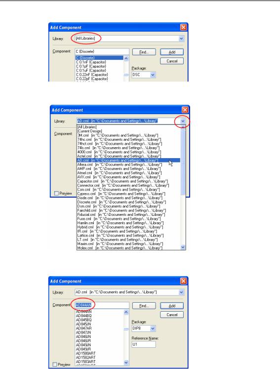
The Add Component dialog will display [All Libraries] in the library path.
We need to swap libraries to use a different one. Click the small ‘down’ arrow on the right side of Libraries: to reveal the fully libraries listing.
From the list, select the AD.cml library.
In the Component: list, type in AD844, this will select the name AD844AN on the list.
Chapter 2 – Schematic Capture Editor 21
Click the Preview button to display previews of the Schematic symbol and PCB footprint.
Click the Add button to add an opamp to the design.
Depending on your current zoom level, you may need to roll the mouse wheel to zoom out a little. You will need to give yourself some space on the design in which to place this new component.
Our Op-Amp (U1) is shown in the design on the end of your cursor as two gates (a & b). Gate a is defined as the logic gate and gate b is the power gate for this component.
Click the mouse once to place the first gate. The second gate (power) will now be dynamic on the end of your cursor ready for placing. Place it near gate a, we will move it later on.
Click the Esc key to cancel this option. Your design should look something like this:

22 Chapter 2 – Schematic Capture Editor
Before we make the connections we should change the component values to be the ones required. This is easy to do because we’ve used ‘generic’ components. If you prefer to use specific Part named components, you can also work this way with PCB Artist.
To edit component Values
Double-click on the Value field (1K), the Text tab of the Properties dialog is displayed.
Click on the Component Values tab.
The Value field shows the current 1K value and is already highlighted. Simply click the Edit button or double-click the blue highlighted field to edit the value required.

Chapter 2 – Schematic Capture Editor 23
Type in 11K.
When done, click the OK button to exit this dialog and OK again to exit Properties. When the value of R2 is changed to 11K the design is updated.
Using the same process (double-clicking on the Value name), edit the Value fields for all R’s and C’s in the design as shown below:
R1 1K |
R2 11K |
R3 1.6K |
|
C1 68nF |
C2 200nF |
C3 0.22uF |
C4 0.22uF |
Our design now looks like this:
If you select the whole component by mistake, you can still edit the Value field by clicking
Component Values tab on the Properties dialog.
To add a drawing border to the design
At any time you can add a drawing border to the design. We will add one now.

24 Chapter 2 – Schematic Capture Editor
Using the Add Component Browser again (<F9>), select the Schema library from the drop down list. For reference, this is a schematic only component library and will not have any PCB symbols associated with them.
Scroll down the list and select the Letter drawing border. This has been previously created to fit a Letter page size.
Like other components, pick Letter from the list or from the preview. Drag it into the design and position it on top of the existing components. You may need to zoom out a bit to see it. Use the <Z> key to zoom out or <A> to view all of the design. For speed you can also roll the mouse wheel.
As with other components, this can be moved later if you need to.