- •Copyright Notice
- •Contents
- •Introduction to PCB Artist
- •Introduction to the Tutorial
- •Additional Help
- •System Requirements
- •Installation
- •Removing the Software
- •Starting PCB Artist
- •The PCB Artist Desktop
- •Toolbars
- •Cancelling Commands
- •Shortcut Keys
- •Units
- •Grids
- •Snapping to Grid
- •Shortcut Menus
- •Undo/Redo
- •Properties of items
- •Status Bar
- •Dockable Windows and Browsers
- •Schematic Design Tutorial
- •Starting a New Schematic
- •Adding Components
- •Placing Components
- •Adding Connections
- •Adding Power & Ground Symbols
- •Adding Connectors
- •Naming Connections
- •Your Schematic is Finished
- •Converting the Schematic to PCB
- •Starting a New PCB Design
- •The New PCB Wizard
- •Schematic Design Completed
- •Getting Started with the Design
- •Converting the Schematic to PCB
- •Changing the Number of Layers
- •Creating a Board Outline Interactively
- •Deleting an existing board outline
- •Adding a new board outline
- •Placing Components
- •Routing the Design
- •Automatic Routing
- •Unrouting the design
- •Manual Routing
- •Summary of the basic modes of routing
- •Picking in tight areas
- •Pouring Copper into Areas
- •Checking the Design Integrity
- •Design Rules Checking
- •Viewing Power Plane Layers
- •Reports, Part Lists and Net Lists
- •Manufacturing the PCB

30 Chapter 2 – Schematic Capture Editor
Click the Save button on the File menu to save the design.
Naming Connections
One last task that is often required is that of naming connections in the design. We’ve added ‘normal’ connections which have been named using the default naming convention and have been given ‘system’ names like N0005, N0100, N008 etc. We’ve also added connections between pins and components that have pre-defined net names (power and ground components, +5V, 0V etc.).
We now need to name a few connections to make them more specific for use in the PCB design.
To edit net names
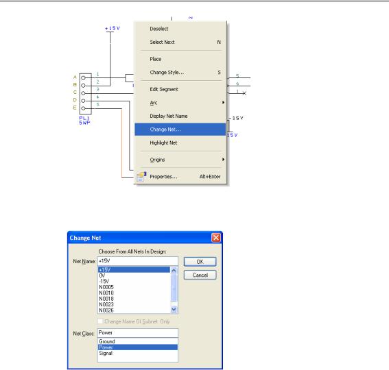
Select the connection just off pin 7 of the Op-Amp’s power gate, the gate marked as U1b. Right click and from the shortcut menu, select Change Net…

Chapter 2 – Schematic Capture Editor 31
From the dialog now displayed, select the Net Name: +15V from the list.
From the Net Class: list, select Power. This will pre-assign you a set of connection properties for this net when it gets used in the PCB portion of the design.
Click OK and return to the design.
If you wish to see the Net Name in the design, right click again with the connection selected and choose Display Net Name from the menu. The net name will now be displayed in the design, you may reposition it if required by picking and dragging it.
If this is difficult to select because you accidentally pick the wrong item, press the <N> key to select Next. The next item in the picking tolerance will be picked.
Now select pin 4 on U1b. Using Change Net again, this time select the net name -15V. Select the Power Net Class again. Click OK to exit this dialog. The Net Name can be displayed using the method above if required.
