- •Copyright Notice
- •Contents
- •Introduction to PCB Artist
- •Introduction to the Tutorial
- •Additional Help
- •System Requirements
- •Installation
- •Removing the Software
- •Starting PCB Artist
- •The PCB Artist Desktop
- •Toolbars
- •Cancelling Commands
- •Shortcut Keys
- •Units
- •Grids
- •Snapping to Grid
- •Shortcut Menus
- •Undo/Redo
- •Properties of items
- •Status Bar
- •Dockable Windows and Browsers
- •Schematic Design Tutorial
- •Starting a New Schematic
- •Adding Components
- •Placing Components
- •Adding Connections
- •Adding Power & Ground Symbols
- •Adding Connectors
- •Naming Connections
- •Your Schematic is Finished
- •Converting the Schematic to PCB
- •Starting a New PCB Design
- •The New PCB Wizard
- •Schematic Design Completed
- •Getting Started with the Design
- •Converting the Schematic to PCB
- •Changing the Number of Layers
- •Creating a Board Outline Interactively
- •Deleting an existing board outline
- •Adding a new board outline
- •Placing Components
- •Routing the Design
- •Automatic Routing
- •Unrouting the design
- •Manual Routing
- •Summary of the basic modes of routing
- •Picking in tight areas
- •Pouring Copper into Areas
- •Checking the Design Integrity
- •Design Rules Checking
- •Viewing Power Plane Layers
- •Reports, Part Lists and Net Lists
- •Manufacturing the PCB
28 Chapter 2 – Schematic Capture Editor
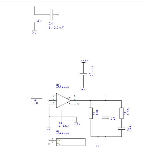
Using our working design, add 2 more 0V symbols. From the Add Component browser, this time add one +15V symbol and place near C3. Now add one -15V symbol, place it near C4.
Drag a connection off the end of the symbol terminal and connect as shown below. Your design will look something like this:
Generally speaking you would now need to add some connector pins to connect the circuit to the outside world.
Adding Connectors
For this example, we will use a connector component from the library.
To add Connector pins
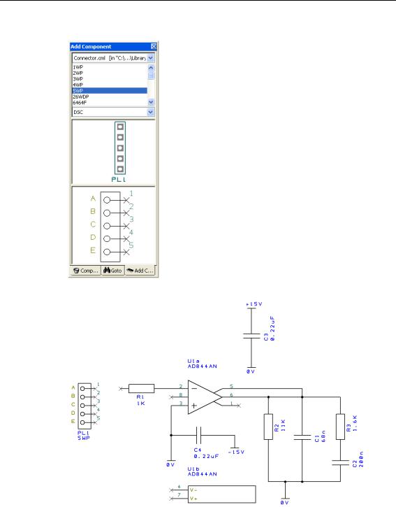
Using the Add Component browser from the Interaction bar <F9>. Choose a new library, select the Conn_std component library.
Chapter 2 – Schematic Capture Editor 29
Select the 5WP connector component from the list. The PCB Symbol and Schematic Symbol previews will be displayed.
Drag it into the design and place it near the resistor R1 as shown below:
Connect in the connector to the design using Add Connection or by dragging off a pin. You will also need to add another +15 component for completeness. Your design should look like this below: