![](/user_photo/1393_G1Syr.jpg)
- •Copyright Notice
- •Contents
- •Introduction to PCB Artist
- •Introduction to the Tutorial
- •Additional Help
- •System Requirements
- •Installation
- •Removing the Software
- •Starting PCB Artist
- •The PCB Artist Desktop
- •Toolbars
- •Cancelling Commands
- •Shortcut Keys
- •Units
- •Grids
- •Snapping to Grid
- •Shortcut Menus
- •Undo/Redo
- •Properties of items
- •Status Bar
- •Dockable Windows and Browsers
- •Schematic Design Tutorial
- •Starting a New Schematic
- •Adding Components
- •Placing Components
- •Adding Connections
- •Adding Power & Ground Symbols
- •Adding Connectors
- •Naming Connections
- •Your Schematic is Finished
- •Converting the Schematic to PCB
- •Starting a New PCB Design
- •The New PCB Wizard
- •Schematic Design Completed
- •Getting Started with the Design
- •Converting the Schematic to PCB
- •Changing the Number of Layers
- •Creating a Board Outline Interactively
- •Deleting an existing board outline
- •Adding a new board outline
- •Placing Components
- •Routing the Design
- •Automatic Routing
- •Unrouting the design
- •Manual Routing
- •Summary of the basic modes of routing
- •Picking in tight areas
- •Pouring Copper into Areas
- •Checking the Design Integrity
- •Design Rules Checking
- •Viewing Power Plane Layers
- •Reports, Part Lists and Net Lists
- •Manufacturing the PCB
![](/html/1393/253/html_p4XN27XnHy.TxXp/htmlconvd-b4Kp6k45x1.jpg)
Chapter 4 – PCB Design Editor 45
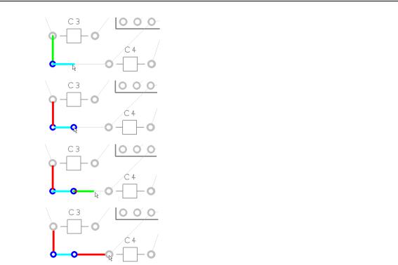
This will either be the next corner or the next location for a via for a layer change. Notice the track has changed color.
Press ‘L’ and <Enter> again to change layers back to the Top layer. Another via is added automatically.
Continue moving the cursor right towards the target pad C4.1. Notice how it is on the Top layer shown in Red.
Once over the target pad, click once to finish the track editing for this connection.
After the track has been added, it can always be modified afterwards by picking and dragging the track or by double-clicking on the track to edit it.
Move onto the next connection for editing.
Summary of the basic modes of routing
During track editing, the basic commands for use are:
Single-Click, once editing, this will insert a corner to change routing direction.
L followed by <Enter> will enable a layer change to the opposite side of the design. This can be used during editing, or afterwards on selection of a track.
To change manual routing modes
You would have been using the standard routing mode of Orthogonal routing (two ‘floating’ segments at 90 degrees to each other).