10.11 Optical Emission, Optical Scattering and Photoemission (B) |
579 |
|
|
Also, the topic of emission is important because it involves applications— fluorescent lighting and television are obviously important and based on emission not on absorption. There are perhaps four principal aspects of optical emission. First, there are many types of transitions allowed. A second aspect is the excitation mechanism that positions the electron for emission. Third are the mechanisms that delay emission and give rise to luminescence. Finally, there are those combinations of mechanisms that produce laser action. Luminescence is often defined as light emission that is not due just to the temperature of the emitting body (that is, it is not black-body emission). There are several different kinds of luminescence depending on the source of the energy. For example, one uses the term photoluminescent if the energy comes from IR, visible, or UV light. Although there seems to be no universal agreement on the terms phosphorescence and fluorescence, phosphorescence is used for delayed light emission and fluorescence sometimes just means the light emitted due to excitation. Metals have high absorption at most optical frequencies, and so when we deal with photoemission, we normally deal with semiconductors and insulators.
10.11.2 Einstein A and B Coefficients (B, EE, MS)
We give now a brief discussion of emission as it pertains to the lasers and masers. The MASER (microwave amplification by stimulated emission of radiation) was developed by C. H. Townes in 1951, also independently by N. G. Basov and A. M. Prokhorov at about the same time). The first working LASER (light amplification by stimulated emission of radiation) was achieved by T. H. Maiman in 1960 using a ruby crystal. Ruby is sapphire (Al2O3) with a small amount of chromium impurities.
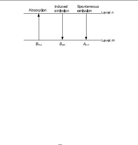
The Einstein A and B coefficients are easiest to discuss in terms of discrete levels, and exhibit a main idea of lasers. See Fig. 10.14. For a complete discussion of how lasers produce intense, coherent, and monochromatic beams of light see the references on applied physics [32–35]. Let the spontaneous emission and the induced transition rates be defined as follows:
Spontaneous emission Induced emission Induced absorption
From the Planck distribution we have for the density of photons
|
ρ(ν) = 8πh3ν 2 |
1 |
|
|
. |
(10.214) |
|
exp(hν |
kT ) −1 |
|
c3 |
|
|
Thus, generalizing to band-to-band transitions, we can write the generation rate as
Gmn = Bmn Nm fm Nn (1− fn )ρ(νmn ) , |
(10.215) |
580 10 Optical Properties of Solids
Fig. 10.14. The Einstein A and B coefficients
where N represents the number and f is the Fermi function. Also, we can write the recombination rate as
Rnm = Bnm Nn fn Nm (1 − fm )ρ(νmn ) + Anm Nn fn Nm (1− fm ) .
In steady state, Gmn = Rnm. From the Fermi function we can show
f |
m |
(1− f |
n |
) |
E |
n |
− E |
m |
|
|
|
|
= exp |
|
|
. |
fn (1− fm ) |
|
|
kT |
|
|
|
|
|
Thus, since Bnm = Bmn, we have from (10.215) and (10.216)
|
|
|
|
|
|
|
|
|
|
E |
n |
− E |
m |
|
|
= Anm , |
Bnm ρ(ν) exp |
|
|
|
−1 |
|
|
kT |
|
|
|
|
|
|
|
|
and
En − Em = hνmn ,
we find for the ratio between the A and B coefficients,
A = 8πn3ν 2 .
B c3
(10.216)
(10.217)
(10.218)
(10.219)
(10.220)
10.11.3 Raman and Brillouin Scattering (B, MS)
The laser has facilitated many optical experiments such as, for example, Raman scattering. We now discuss briefly Raman and Brillouin scattering. One refers to the inelastic scattering of light by phonons as Raman scattering if optical phonons are involved, and Brillouin scattering if acoustic phonons are. If phonons are emitted one speaks of the Stokes line and if absorbed as the anti-Stokes line. Note that these processes are two-photon processes (there is one photon in and one out). Raman and Brillouin scattering are made possible by the strain dependence of the electronic polarization. The relevant conservation equations can be written:
ωk = ωk′ ±ωK , |
(10.221) |
k = k′ ± K , |
(10.222) |
10.11 Optical Emission, Optical Scattering and Photoemission (B) |
581 |
|
|
where ω and k refer to photons and ωK and K to phonons. Since the value of the wave vector of photons is very small, the phonon wave vector can be at most twice that of the photon, and hence is very small compared to the Brillouin zone width. Hence, the energy of the optical phonons is very nearly constant at the optical phonon energy of zero wave vectors.
Brillouin scattering from longitudinal acoustic waves can be viewed as scattering from a density grating that moves at the speed of sound. Raman scattering can be used to determine the frequency of the zone-center phonon modes. Since the processes depend on phonons, a temperature dependence of the relative intensity of the Stokes and anti-Stokes lines can be predicted.
A simple idea as to the temperature dependence of the Stokes and the antiStokes lines is as follows [23, p. 323]. (For a more complete analysis see [10.2, p272]. See also Fox op. cit. p222.)
Stokes: |
Intensity n |
K |
+1 a† |
n |
2 |
n |
K |
+1 , |
|
|
|
|
k |
|
K |
|
|
Anti-Stokes: |
|
Intensity nK −1 ak nK |
2 nK |
|
|
I (ω +ωK ) |
= |
nK |
|
= exp(− βΩ) . |
|
|
|
nK +1 |
|
|
I (ω −ωK ) |
|
|
|
|
|
|
(10.223)
(10.224)
(10.225)
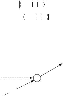
A diagram of Raman/Brillouin scattering involving absorption of a phonon (anti-Stokes) is shown in Fig. 10.15. As we have shown above, the intensity of the anti-Stokes line goes to zero at absolute zero, simply because there are no phonons available to absorb.
ω′, k′ photon
ω, k photon

 E, K phonon
Fig. 10.15. Raman and Brillouin scattering. The diagram shows absorption. Acoustic phonons are involved for Brillouin scattering, and optical phonons for Raman
An expression for the frequency shift of both of these processes is now given. For absorption
k + K = k′ , |
(10.226) |
and |
|
ωk +ωK =ωk′ . |
(10.227) |
582 10 Optical Properties of Solids
Assuming the wavelength of the phonon is much greater than the wavelength of light, we have k k′. If we let θ be the angle between k and k′, then it is easy to see that
θ |
|
(10.228) |
K = 2k sin |
2 |
. |
|
|
|
The shift in frequency of the scattered light is ωK. For Brillouin scattering, with VωK/K being the phonon velocity and n being the index of refraction, one finds
|
|
|
2nωkV |
θ |
|
|
|
ωK |
= |
|
sin |
|
, |
(10.229) |
|
c |
2 |
|
|
|
|
|
|
|
and thus n can be determined. When phonons are absorbed, the photons are shifted up in frequency by ωK, and when phonons are emitted, they are shifted down in frequency by this amount.
10.12Magneto-Optic Effects: The Faraday Effect (B, EE, MS)
The rotation of the plane of polarization of plane-polarized light, which is propagating along an external magnetic field, is called the Faraday effect.6 Substances for which this occurs naturally without an applied field are said to be optically active. One way of understanding this effect is to resolve the plane-polarized light into counterrotating circularly polarized components. Each component will have (see below) a different index of refraction and so propagates at a different speed, thus when they are recombined, the plane of polarization has been rotated. The two components behave differently because they interact with electrons via the two rotating electric fields. The magnetic field in effect causes a different radial force depending on the direction of rotation, and this modifies the effective spring constant. Both free and bound carriers can contribute to this effect. A major use of the Faraday effect is as an isolator that allows electromagnetic waves to propagate only in one direction. If the wave is polarized, and then rotated by 45 degrees by the Faraday rotator, any wave reflected back through the rotator will be rotated another 45 degrees in the same direction and hence be at 90 degrees to the polarizer and so cannot travel that way.
A simple classical picture of the effect works fairly well. We assume an electron bound by an isotropic Hooke’s law spring in an electric and a magnetic field. By Newton’s second law (e > 0):
mr = −kr − e(E + r × B) . |
(10.230) |
6 A comprehensive treatment has been given by Caldwell [10.5].
10.12 Magneto-Optic Effects: The Faraday Effect (B, EE, MS) 583
Defining ω02 = k/m (a different use of ω0 from that in (10.108)!), letting B = Bk, and assuming the electric field is in the (x,y)-plane, if we write out the x and y components of the above equation we have
|
|
|
|
|
|
|
|
|
|
|
x + |
e |
yB +ω02 x = − |
e |
Ex , |
(10.231) |
|
m |
m |
|
|
|
|
|
|
|
|
y − |
|
e |
xB +ω02 y = − |
e |
|
Ey . |
(10.232) |
|
|
m |
|
|
|
|
|
|
m |
|
|
We define w± = x ± iy and E± = Ex ± iEy. Note that the real and imaginary parts of E+ correspond to “right-hand waves” (thumb along z) and the real and imaginary parts of E− correspond to “left-hand waves”.
We assume for the two circularly polarized components,
E± = E0 exp[±i(ωt − k± z)] , |
(10.233) |
which when added together gives a plane-polarized beam along x at z =0. We seek steady-state solutions for which
w± = exp[±i(ωt − k± z)] . |
(10.234) |
Substituting we find |
|
|
|
w± = |
(−e / m)E± |
|
|
. |
(10.235) |
(ω02 −ω2 ) ± (e / m)Bω |
The polarization P is given by |
|
|
|
|
P = −Ner , |
(10.236) |
where N is the number of electrons/volume:
P± = |
(Ne2 / m)E± |
|
(ω02 −ω2 ) ± (e / m)Bω . |
(10.237) |
It is convenient to write this in terms of two special frequencies. The cyclotron frequency is
|
|
ωc |
= eB |
, |
|
|
|
(10.238) |
|
|
|
|
m |
|
|
|
|
|
and the plasma frequency is |
|
|
|
|
|
|
|
|
|
|
ωp = |
Ne2 |
. |
|
(10.239) |
|
mε0 |
|
|
|
|
|
|
|
|
Thus (10.237) can be written |
|
|
|
|
|
|
|
|
|
|
|
|
ε ω2 E |
± |
|
|
|
P± = |
|
|
|
0 p |
|
|
. |
(10.240) |
|
(ω2 |
−ω2 ) ± |
ω ω |
|
0 |
|
|
|
|
c |
|
As usual we write |
|
|
|
|
|
|
|
|
|
D± = ε0E± + P± , |
(10.241) |
584 10 Optical Properties of Solids
or
D± = ε±E± .
Using (10.240), (10.241), (10.242), and
n2 = ε± ,
± ε0
we find
|
n2 |
=1+ |
|
ω2p |
. |
|
(ω2 |
−ω2 ) ±ω ω |
|
± |
|
|
|
|
0 |
c |
|
The total angle that the polarization turns through is
Θ = 12 (Θ+ −Θ−) , where in a distance l (and with period of rotation Τ)
|
l |
ωl |
|
ωl |
n± . |
Θ± = 2π |
|
= v |
|
= |
c |
v Τ |
± |
± |
|
|
|
|
Thus,
Θ = 12 ωcl (n+ − n−) .
If
ω2p << (ω02 −ω2 ) ±ωcω ,
then
|
|
|
|
|
n 1+ 1 |
|
ω2p |
. |
|
|
± |
2 (ω2 |
−ω2 ) ±ω ω |
|
|
0 |
c |
|
So, combining (10.247) and (10.249)
|
ω ω2ω2l |
1 |
|
|
Θ = − |
c p |
|
. |
2c |
|
(ω02 −ω2 )2 |
−ωc2ω2 |
|
|
|
For free carriers ω0 = 0, we find if ωc << ω,
lω2ω
Θ = − p c . 2cω2
(10.242)
(10.243)
(10.244)
(10.245)
(10.246)
(10.247)
(10.248)
(10.249)
(10.250)
(10.251)
Note a positive B (along z) with propagation along z will give a negative Verdet constant (the proportionality between the angle and the product of the field and path length) and a clockwise Θwhen it is viewed along (i.e. in the direction of) −z.
Problems 585
Problems
10.1In a short paragraph explain what photoconductivity is, and describe any photoconductivity experiment.
10.2Describe, very briefly, the following magneto-optical effects: (a) Zeeman effect, (b) inverse Zeeman effect, (c) Voigt effect, (d) Cotton–Mouton effect,
(e) Faraday effect, (f) Kerr magneto-optic effect.
Describe briefly the following electro-optic effects: (g) Stark effect, (h) inverse Stark effect, (i) electric double refraction, (j) Kerr electro-optic effect.
Descriptions of these effects can be found in any good optics text.
10.3Given a plane wave E = E0exp[i(k·r − ωt)] normally incident on a surface, detail the assumptions, conditions and steps to show ncE0 = E1 − E2, (cf. (10.26)).
10.4(a) From [x, px] = i , show that
[H ,eˆ r]= − im eˆ p ,
(b) For eˆ = ˆi, show the oscillator strength fij obeys the sum rule ∑jfij = 1.
10.5For intermediate frequencies ωT < ω < ωL, given (by (10.198))
ε(ω) |
− |
ε(∞) |
= |
|
|
|
|
|
|
3Bion (ω) |
|
|
, |
ε |
0 |
ε |
0 |
[1− B |
el |
− B (ω)](1− B |
el |
) |
|
|
|
|
|
|
|
ion |
|
|
and the equation of motion (by (10.199)) |
|
|
|
|
|
|
μv + Gv = |
1 |
|
|
|
Ne2 |
v + eE , |
|
|
|
|
|
3ε |
0 |
1 |
− B |
|
|
|
|
|
|
|
|
|
|
|
|
|
|
|
|
|
|
|
|
|
|
|
|
|
el |
|
|
|
|
derive the equation
ωT2 + εc(ε∞0) = ωL2 ,
where c is a defined as constant within the derivation. In this process, show intermediate derivations for the following equations defining constants as necessary:
μ(ωT2 −ω2 )v = eE ,
|
E |
= |
|
|
1 |
|
, |
|
|
Eloc |
1 |
+ F |
|
|
|
|
ε(ω) = ε(∞) + |
|
|
cε0 |
|
|
. |
|
ωT2 −ω2 |
586 10 Optical Properties of Solids
10.6This problem fills in the details of Sect. 10.11.2.
(a) Describe the factors that make up the generation rate
Gmn = Bmn Nm fm Nn (1− fn )ρ(νmn ) .
(b) Show from the Fermi function that
f |
n |
(1− f |
m |
) |
E |
m |
− E |
n |
|
|
|
|
= exp |
|
|
. |
fm (1− fn ) |
|
kT |
|
|
|
|
(c) Starting from Gmn = Rnm, show that
A = 8πn3ν 2 .
B c3
11 Defects in Solids
11.1 Summary About Important Defects (B)
A defect in a solid is any deviation from periodicity in the solid. All solids have defects, but for some applications, they can be neglected, while for others, the defects can be very important. By now, simple defects are well understood, but for more complex defects, a considerable amount of fundamental work remains to be accomplished for a thorough understanding.
Some discussion of defects has already been made. In Chap. 2, the effects of defects on the phonon spectrum of a one-dimensional lattice were discussed, whereas in Chap. 3 the effects of defects on the electronic states in a onedimensional lattice were considered. In the semiconductor chapter, donor and acceptor states were used, but some details were postponed until this chapter.
There is only one way to be perfect, but there are numerous ways to be imperfect. Thus, we should not be surprised that there are many kinds of defects. The mere fact that no crystal is infinite is enough to introduce surface defects, which could be electronic or vibrational. Electronic surface states are classified as Tamm states (if they are due to a different potential in the last unit cell at the surface edge with atoms far apart) or Shockley states (the cells remain perfectly repetitive right up to the edge, but with atoms close enough so as to have band crossing1). Whether or not Tamm and Shockley states should be distinguished has been the subject of debate that we do not wish to enter into here. In any case, the atoms on the surface are not in the same environment as interior atoms, and so, their contribution to the properties of the solid must be different. The surface also acts to scatter both electrons and phonons. The properties of surfaces are of considerable practical importance. All input and output to solids goes through the surfaces. Thermionic and cold field emission from surfaces is discussed in Sects. 11.7 and 11.8. Surface reconstruction is discussed in Chap. 12. Another important application of surface physics is to better understand corrosion.
Besides surfaces, we briefly review other ways crystals can have defects, starting with point defects (see Crawford and Slifkin [11.7]). When a crystal is grown, it is not likely to be pure. Foreign impurity atoms will be present, leading to substitutional or interstitial defects (see Fig. 11.1). Interstitial atoms can originate from atoms of the crystal as well as foreign atoms. These may be caused by thermal effects (see below) or may be introduced artificially by radiation damage. Radiation damage (or thermal effects) may also cause vacancies. Also,
1 See, e.g., Davison and Steslicka [11.8].
when a crystal is composed of more than one element, these elements may not be exactly in their proper chemical proportions. The stoichiometric derivations can result in vacancies as well as antisite defects (an atom of type A occupying a site normally occupied by an atom of type B in an AB compound material).
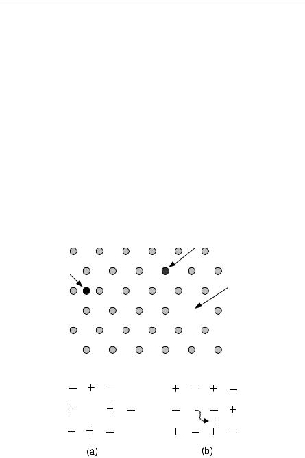
Vacancies are always present in any real crystal. Two sorts of point defects involving vacancies are so common that they are given names. These are the Schottky and Frenkel defects, shown for an ionic crystal in Fig. 11.2. Defects such as Schottky and Frenkel defects are always present in any real crystal at a finite temperature in equilibrium. The argument is simple. Suppose we assume that the free energy F = U − TS has a minimum in equilibrium. The defects will increase U, but they cause disorder, so they also cause an increase in the entropy S. At high enough temperatures, the increase in U can be more than compensated by the decrease in −TS. Thus, the stable situation is the situation with defects.
Mass transport is largely possible because of defects. Vacancies can be quite important in controlling diffusion (discussed later in Sect. 11.5). Ionic conductivity studies are important in studying the motion of lattice defects in ionic crystals. Color centers are another type of point defect (or complex of point defects). We will discuss them in a little more detail later (Sect. 11.4). Color centers are formed by defects and their surrounding potential, which trap electrons (or holes).
Substitutional
Interstitial
Vacancy
Fig. 11.1. Point defects
Fig. 11.2. (a) Schottky and (b) Frenkel defects