

water quality and system
.pdf< previous page |
page_42 |
next page > |
Page 42
Mechanical Joints
There are several types of mechanical joints which are a combination of a bell and spigot. A ring on both ends have holes. Threaded rods run through the holes and the joint is held closed with nuts placed on the rods. Mechanical joints are effective beginning at the 6-inch pipe size up to 48-inch diameter size.
Compression Joints
In smaller sizes, up to about 4 inches in diameter, compression joints are used with fittings. Compression joints use a union to join two pieces of pipe together in a place where they can be taken apart and put together again. In the union, two plates press together using a threaded collar. The force of the threaded collar holds two pipes together with such force that there is no leak. The advantage of a compression fitting is that it can be taken apart quickly and reassembled many times. The largest pipe union is about 2-1/2 inches in diameter. Threaded joints, on the other hand, have a tendency to leak if taken apart and reassembled many times.
Flanged Joints
Flanged joints are used in mechanical rooms because they are readily disassembled and re-assembled during maintenance. Often, large valves are installed with flanged joints to facilitate quick removal and reassembly. A flanged joint is made up with a gasket between the flanges. The flanges can be screwed or welded onto the pipe. The flanges are expensive, however, and increase the costs of the installation. In general, flanged joints are easier to break and reassemble than mechanical joints. Large crescent, socket or open-ended wrenches are used to take apart these joints and there should be enough open space around the entire joint for free movement of the socket or crescent wrench used. The smallest flanged joint is for one-inch diameter pipe.
Welded Joints
Finally, joints in steel pipe are welded. The pipe is cut to length with a cutting torch and successive sections are welded in place. Sometimes, a machine is used to weld the joint while in other cases a welderusing a metal arc or metal-in-gas welding equipmentfuses the joints together. Welded joints are the strongest and are used for joining high-pressure steam and compressed air systems. Welded joints are also used for water systems. Usually, welded joints
< previous page |
page_42 |
next page > |

< previous page |
page_43 |
next page > |
Page 43
are fabricated on the jobsite and fitted up as they are welded together. Welded joints, obviously, are not intended to be disassembled. Many facilities use a combination of flanged joints and welded joints for their pipe systems.
Pumps
A centrifugal pump uses an electric motor to turn a shaft that has a blade. The blades (called impellers) push the water through them. Centrifugal pumps come in all sizes and shapes and are manufactured for numerous special applications. The size of the motor determines the amount of flow and the increase in water pressure.
All centrifugal pumps have a relationship between the pressure increase and the amount of flow. Example: As the pressure increases on a pump, the flow through it decreases. A simplified pump curve is shown in Figure 3-4. At a certain point, the pump cannot push the water higher and at another point, it cannot move any greater flow. These are the ends of the curve for that specific pump. Engineers select pumps that have the best efficiency between the ends of the curve, which saves the client money on energy costs.
A cutaway section of a pump is shown in Figure 3-5. The drawing shows the shaft, impeller and casing.
As with the previous discussion for pipe, there is a tremendous variety of centrifugal pumps constructed of a wide variety of materials. The materials affect the costs of pumps significantly. However, facility managers should be aware that the electricity purchased to drive a pump far exceeds the cost of the pump itself during its life. The facility manager is far ahead by spending slightly more for a more energy-efficient, low-maintenance pump than to try to save a few dollars on the initial purchase.
Pipe and Pump Cost Tradeoffs
The question of energy costs raises an interesting point that exists between the costs of the piping and the costs of pumping.
< previous page |
page_43 |
next page > |

< previous page |
page_44 |
next page > |
Page 44
Figure 3-4.
Pump performance curve. Courtesy: Mechanical Engineering Reference
Manual, Michael R. Lindburg, PE, Professional Publications, Inc., Belmont, CA, 1994.
Just imagine for a moment a big pump pushing water through a tiny pipe. The pipe is so small that it takes a very powerful pump to push the water through it to the users.
On the other hand, imagine for a moment a large pipe, being supplied with a small pump. In this case, the pump is quite undersized for the intended service.
Given these two extremes, the designer of a water system wants to optimize the investment in both pipes, pumps and electrical energy costs. Overall, the optimum combination of pipe size, pump cost, and energy determine the overall system costs.
To analyze the tradeoffs between pipe costs and pumping costs, the designer needs to know 1) the facilities' electrical energy costs and 2) the expected life of the pipe system. The designer should already have an estimate of pipe and pump costs and often makes assumptions for the owner about energy and life. However, for a long-life project, the electrical energy costs affect the options more significantly than for a short life.
Given the state of modern mathematical modeling techniques and personal computers, it is possible for the facility planner to analyze many scenarios and select the most attractive option.
< previous page |
page_44 |
next page > |

< previous page |
page_45 |
next page > |
Page 45
Figure 3-5.
Cutaway view of a pump impeller. Reprinted from Fluid Mechanics with Engineering Applications with permission from McGraw-Hill Book Co., New York City.
Utility construction costs are high because the cost of power for pumping is projected several years into the future. By increasing pipe diameter, energy costs are reduced because less energy is needed to push water through large pipes than through small ones. Increasing the pipe diameter, while costly for large systems, will pay for itself with in reduced energy costs over the system's life.
Pump Operational Problems
The two most common problems with centrifugal pumps are with the pump seals and with debris in the pump impeller blades.
Pump Seal Problems
Probably more frustration and agony has occurred by facility managers over pump seals than with any other water system management problems.
The shaft from the motor to the impeller must be separated from the fluid by a seal. The seal prevents water/liquid from leaking out of the pump. Thanks to many long hours spent by engineers and designers, today the design of seals for water pumps is excellent.
< previous page |
page_45 |
next page > |

< previous page |
page_46 |
next page > |
Page 46
However, seals still have to be maintained and changed/repaired on a routine basis. When a pump seal fails, the pump has to be taken out of service for repair. If this happens when somebody in the facility wants to use water, there will be a significant number of complaints. To prevent these, most systems are designed with a pair of pumps that can alternate. When one pump is taken out of service for seal repairs, or any other reason, the other pump continues to provide the facility with the necessary water and pressure needed for operations. Depending upon the size of the pump and how easy it is for maintenance crews to work on it, a pump seal can be changed in an hour, or it can take an entire day. Some facilities keep a spare pump on hand and when maintenance is needed, the entire pump is pulled along with the motor, and a spare one is dropped into place. The original pump is serviced, and placed back into spares.
Many facilities standardize their pump sizes to reduce the need for spares throughout the complex.
Pump Plugging Problems
The other most frequent problem encountered with centrifugal pumps is one of plugging with debris, dirt, rocks or other material that either goes into the pump body and either is caught by the impeller blades or plugs the piping. A device is usually installed upstream of the pump to strain out this debris. Not surprisingly, it is called a strainer (see Figure 3-6).
A strainer consists of a wire basket that sits inside a bucket in the piping. The basket's tiny holes are sized to catch particles large enough to bind or harm the pump's impeller. The basket is set into a chamber and is removed for cleaning when plugged with debris. The strainer is usually isolated from the pipe with valves to prevent draining the line when the basket is cleaned. The strainer can be bypassed for a short time while the basket is being changed or the system can use what is called a duplex strainer where one basket is working while the pump is running while the second is cleaned.
Pump Suction and Priming
The two types of pump installations are called flooded suction and non-flooded suction. For the easiest maintenance, a pump with a non-flooded suction is best. This way, when the pump is off, the water runs back into the piping or reservoir, leaving the piping dry
< previous page |
page_46 |
next page > |

< previous page |
page_47 |
next page > |
Page 47
and reducing the mess that accompanies changing out pump parts.
A flooded suction is isolated from the reservoir or upstream piping with valves, but this type of installation will be full of water when the system is shut down, and provisions must be made to drain this water when pipe lines are pulled apart to remove the pump.
Pumps can become vapor-locked when the water does not fill up the casing where the impeller is located. The pump turns, but water is not moved because the spaces are filled with air. Most pumps are self-priming and will suck the water into the impeller when they start. The key to self-priming is tight seals. In general, a leaky pump will not prime itself.
Figure 3-6.
A pipe strainer for a large swimming pool. The strainer protects the pump impeller and seals from debris.
Quite often, the pump is designed to sit at floor level, just a few inches above the reservoir or the natural pressure of the water. These non-flooded suction pumps are close enough to the reservoir that they will self-prime and free drain. For maintenance, this is the ideal pump installation.
A pump that will not self prime can be primed by flooding the impeller with a hose or other source. Once running, it will maintain itself indefinitely. However, maintenance forces have to constantly re-prime the pump if the power fails and the pump shuts off.
For a complete discussion of maintenance of pumps, pipes and water systems, see Chapter 14.
Tanks
Just as water is pumped through pipes to where it needs to be, tanks are used to store it for later use. The most common tanks encountered by facility managers are hot water tanks. These tanks store up an adequate amount of hot water to be used by the facility when needed (see Chapter 6 for more on hot water systems).
< previous page |
page_47 |
next page > |

< previous page |
page_48 |
next page > |
Page 48
In addition to hot water tanks, which are insulated with foam or fiberglass, elevated water storage tanks provide water for commercial and residential use. These large tanks are usually under the control of the water utility, but the facility manager may have to manage one or two. In some large buildings, tanks are installed to provide water supply near the point of use (see Figure 3-7).
Just as pumps are coordinated with pipe size in a matter of economics, tanks can be utilized in a water system to reduce the size of the pipe between two points. The tank then stores up water during periods of low demands and distribution pipes are supplied from the tanks when demands are high. In order to provide enough pressure for the distribution system, tanks are often elevated. The purpose of elevating the tanks means that the water does not have to be pumped after it leaves the tank. Water is heavy and an above ground elevated tank is subject to large weights. Design of elevated tanks is a specialty. One other problem with elevated tanks is their tendency to freeze if the water is stagnant in them for an extended period during cold winter seasons.
Fresh water tanks can be installed in high rise buildings to balance out pressures for a few floors.
Concrete or steel tanks provide the most economical, attractive combination of life and cost. Many tanks are lined. That is the inside of the tank is coated with epoxy or another inert material to protect the system from rust or leaks.
Since large water tanks are critical to a city utility, codes for tank design are rigorous and make the tanks relatively expensive. The tank must be strong enough to hold the internal pressures of the water. Tanks must be checked to confirm they meet seismic requirements for the areas where they are constructed. In addition, tanks have to have the associated piping coordinated to get the water into the tanks and out again.
Finally, tanks need hatches for access to allow the tanks to be inspected and ladders must be provided, if the tank is above ground, to allow maintenance personnel to get to the hatches. Many tanks have instruments that provide operators with the temperatures and the water levels inside.
< previous page |
page_48 |
next page > |

< previous page |
page_49 |
next page > |
Page 49
Figure 3-7.
An above-ground utility water tank. The small blockhouse encloses a fire water pump capable of pumping 1,200 gallons per minute.
Valves
Valves are used to control flows and to shut off flows from pipes. As with the previous discussions with pipe and pumps, there are many types of valves and their application is as varied. Valves can also be operated by hand, with electricity to open, close and vary flows, or valves can be operated with air pressure (pneumatically). Air pressure operated valves work very well to control varying flows. These types of valves are usually installed in combination with a flow meter. The meter reads the flow and sends an electric signal to a device that controls the size of the opening of the valve. If more flow is required, changes allow the valve to open more; if less flow is needed, the valve is closed slightly.
Past use of computers and industrial application has caused tremendous growth in these types of valves and their servicing is not usually done with plumbers since electronics and pneumatics control the valves. A fairly common type of valve in a pipe system is called a solenoid valve. Solenoid refers to the device that controls the valve (generic term is actuator.) Solenoid-operated valves are either open or closed.
Hand valves are still used, of course. The three most common
< previous page |
page_49 |
next page > |
< previous page |
page_50 |
next page > |
Page 50
types of valves are still gate valves, globe valves, and ball valves (see Figures 3-8, 3-9 and 3-10).
Gate Valve
The original valve is called a gate valve (see Figure 3-8). The gate valve is just that, a gate. With a series of threads on the stem of the gate, a handwheel is used to lower or raise the gate and increase or decrease the flow.
The problem with the gate valve is that for a low-flow application, the gate throttles off most of the flow. This will cause the valve to whistle or whine, indicating extreme wear on the gate. A lot of pressure will be lost when a gate is throttled to near zero flow.
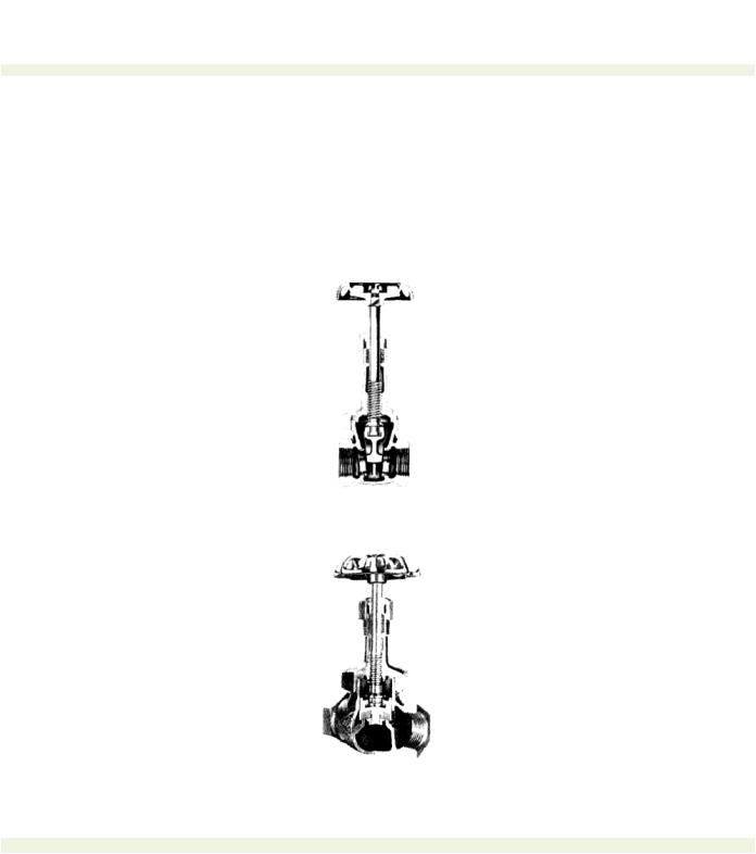
Globe Valve
As a result of operational problems with gate valves, the globe valve was invented (see Figure 3-9). The globe valve, instead of a fiat plate as the gate valve, is a round disk that sits fiat on a round hole in the valve body. As the stem screws up and down, flow is even around the fiat disk. Most garden hose and sink faucets are globe valves.
Globe valves and gate valves always seem to have a problem with leaking around the stem. Gate valves are especially notorious but these
Figure 3-8.
A gate-type valve. Reprinted from Lyons
Encyclopedia of Valves with permission,
Van Nostrand-Reinhold, 1975.
Figure 3-9.
A globe-type valve. Reprinted from Lyons
Enclopedia of Valves with permission,
Van Nostrand-Reinhold Company.
< previous page |
page_50 |
next page > |

< previous page |
page_51 |
next page > |
Page 51
can usually be fixed in a half-hour or so.
Ball Valves
Finally, the favored application for most small systems is the ball valve. The ball valve is so called because a ball with a hole in it is used for flow control. When the valve is open, the hole in the ball is lined up with the pipe. To close, the ball valve the ball is turned so that the hole in the ball is crosswise with the pipe and there is no flow. Ball valves are not used for throttling; they are usually open or closed. Ball valves are favored by mechanics because they are very smooth-acting and easy to operate.
Figure 3-10.
A ball-type valve. Reprinted from Lyons Encyclopedia of
Valves with permission of Van Nostrand-Reinhold Company,
New York City, 1975. Original illustration from Chemetron
Corporation, Fluid Controls Division.
Fixtures
Another major element of a water system is combined under the broad heading of fixtures. Fixtures for water and pipe systems are where the people come into contact with the water. Fixtures include all of bathroom and kitchen items along with a few special items. Fixtures include sinks, toilets, faucets, wash basins, slop sinks, urinals, bidets, bathtubs and showers. Common elements to most fixtures are that they are constructed of a nonabsorbing material such as stainless steel or porcelain, hard plastic, stone, brass or bronze. The materials will not corrode in the wet environment, and are smooth for easy cleaning and sterilizing. People use fixtures and water to clean food, wash, bathe and eliminate.
One reason for successful health in advanced countries stems from the health benefits derived from the effective use of fixtures to prevent spreading of diseases between individuals. Bathrooms where people are able to wash and bathe prevents the spread of many contagious diseases common in non-industrialized nations.
< previous page |
page_51 |
next page > |