

Laser-Tissue Interactions Fundamentals and Applications - Markolf H. Niemz
.pdf58 3. Interaction Mechanisms
According to Karu (1987), local wound healing e ects with helium–neon or diode lasers may be explained by the action of low-intensity light on cell proliferation. In the area of such injuries, conditions are usually created preventing proliferation such as low oxygen concentration or pH. The exposure to red or near infrared light might thus serve as a stimulus to increase cell proliferation. When irradiating fresh wounds, though, the e ect of biostimulation is found to be minimal or even nonexistent. This observation is probably due to the fact that cell proliferation is very active in fresh wounds, and regeneration is not significantly altered by laser irradiation.
One remaining open question is, which of the characteristics of laser radiation – coherence, narrow bandwidth, polarization – is of primary importance for biostimulation? Or, in other words, does it necessarily have to be a laser or would an incoherent light source serve as well? Hence, biostimulation is still a research field with a lot of speculation involved. Usually, the controversy stems from our inability to specify the photochemical channels of potential reactions. Detailed investigations in this area and reproducible experimental results are badly needed.
3.1.3 Summary of Photochemical Interaction
• Main idea: |
using a photosensitizer acting as catalyst |
|
(only in photodynamic therapy) |
• Observations: |
no macroscopic observations |
• Typical lasers: |
red dye lasers, diode lasers |
• Typical pulse durations: |
1s... CW |
• Typical power densities: |
0.01 ... 50W/cm2 |
• Special applications: |
photodynamic therapy, biostimulation |
3.2 Thermal Interaction
The term thermal interaction stands for a large group of interaction types, where the increase in local temperature is the significant parameter change. Thermal e ects can be induced by either CW or pulsed laser radiation. While photochemical processes are often governed by a specific reaction pathway, thermal e ects generally tend to be nonspecific according to Parrish and Deutsch (1984). However, depending on the duration and peak value of the tissue temperature achieved, di erent e ects like coagulation, vaporization, carbonization, and melting may be distinguished. In the following paragraphs, these e ects shall first be visualized by selected photographs taken with either light microscopy or scanning electron microscopy (SEM). Afterwards, detailed models of heat generation, heat transport, and associated heat e ects are given. Finally, the principles of laser-induced interstitial thermotherapy
– a recently established treatment technique – are discussed.
3.2 Thermal Interaction |
59 |
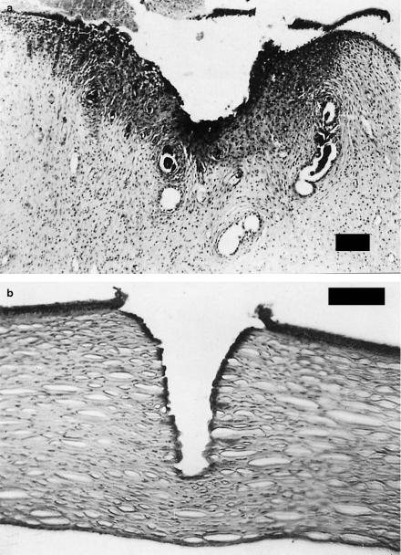
Coagulation. The histologic appearance of coagulated tissue is illustrated in Figs. 3.10a–b. In one case, a sample of uterine tissue was coagulated using a CW Nd:YAG laser. In a histologic section, the coagulated area can be easily detected when staining the tissue with hematoxylin and eosin. Coagulated tissue appears significantly darker than other tissue. In the second photograph, 120 pulses from an Er:YAG laser were applied to an excised cornea. Again, the tissue was stained with hematoxylin and eosin. During the process of coagulation, temperatures reach at least 60◦C, and coagulated tissue becomes necrotic as will be discussed in this section.
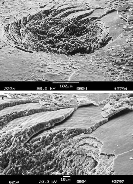
Vaporization. Another example of an important thermal e ect is shown in Figs. 3.11a–b. A tooth was exposed to 20 pulses from an Er:YAG laser. During the ablation process, complete layers of tooth substance were removed leaving stair-like structures. This observation is attributed to the existence of so-called striae of Retzius which are layers with a high content of water molecules. Water strongly absorbs the Er:YAG wavelength at 2.94μm as shown below, thus leading to vaporization within these layers. The induced increase in pressure – water tries to expand in volume as it vaporizes – leads to localized microexplosions with results as demonstrated in the enlargement in Fig. 3.11b. In the literature, vaporization is sometimes also referred to as a thermomechanical e ect due to the pressure build-up involved. The resulting ablation is called thermal decomposition and must be distinguished from photoablation which will be described in Sect. 3.3.
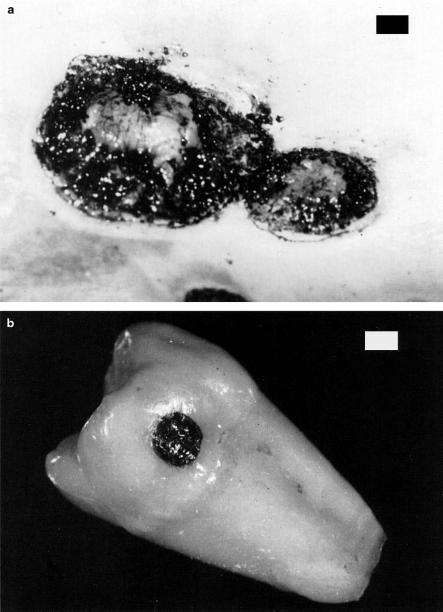
Carbonization. In Fig. 3.12a, a sample of skin is shown which was exposed to a CW CO2 laser for the purpose of treating metastases. In this case, however, too much energy was applied and carbonization occurred. Thus, the local temperature of the exposed tissue had been drastically increased. At temperatures above approximately 100◦C, the tissue starts to carbonize, i.e. carbon is released, leading to a blackening in color. A similar e ect is seen in Fig. 3.12b, where a tooth was exposed to a CW CO2 laser. For medical laser applications, carbonization should be avoided in any case, since tissue already becomes necrotic at lower temperatures. Thus, carbonization only reduces visibility during surgery.
Melting. Finally, Figs. 3.13a–b show the surface of a tooth after exposure to 100 pulses from a Ho:YAG laser. In Fig. 3.13a, several cracks can be seen leaving the application spot radially. They originate from thermal stress induced by a local temperature gradient across the tooth surface. The edge of the interaction zone is shown in an enlargement in Fig. 3.13b. Melted and afterwards down-cooled tooth substance as well as gas bubbles are observed similar to solidified lava. The temperature must have reached a few hundred degrees Celsius to melt the tooth substance which mainly consists of hydroxyapatite, a chemical compound of calcium and phosphate as will be discussed in Sect. 4.2. Obviously, the pulse duration of a few microseconds is still long enough to enable a su cient increase in temperature, since the applied repetition rate of 1Hz is extremely low.
60 3. Interaction Mechanisms
Fig. 3.10. (a) Uterine tissue of a wistar rat coagulated with a CW Nd:YAG laser (power: 10W, bar: 80μm). Photograph kindly provided by Dr. Kurek (Heidelberg).
(b) Human cornea coagulated with 120 pulses from an Er:YAG laser (pulse duration: 90μs, pulse energy: 5mJ, repetition rate: 1Hz, bar: 100μm)
3.2 Thermal Interaction |
61 |
Fig. 3.11. (a) Human tooth vaporized with 20 pulses from an Er:YAG laser (pulse duration: 90μs, pulse energy: 100mJ, repetition rate: 1Hz). (b) Enlargement showing the edge of ablation
62 3. Interaction Mechanisms
Fig. 3.12. (a) Tumor metastases on human skin carbonized with a CW CO2 laser (power: 40W, bar: 1mm). Photograph kindly provided by Dr. Kurek (Heidelberg).
(b) Human tooth carbonized with a CW CO2 laser (power: 1W, bar: 1mm)

3.2 Thermal Interaction |
63 |
Fig. 3.13. (a) Human tooth melted with 100 pulses from a Ho:YAG laser (pulse duration: 3.8μs, pulse energy: 18mJ, repetition rate: 1Hz). (b) Enlargement showing the edge of the melted zone
64 3. Interaction Mechanisms
Temperature certainly is the governing parameter of all thermal laser– tissue interactions. And, for the purpose of predicting the thermal response, a model for the temperature distribution inside the tissue must be derived. Before we start working on this task, let us first look at the basics of what happens during thermal interaction.
At the microscopic level, thermal e ects have their origin in bulk absorption occurring in molecular vibration–rotation bands followed by nonradiative decay. The reaction with a target molecule A can be considered as a twostep process. First, absorption of a photon with an energy hν promotes the molecule to an excited state A ; and second, inelastic collisions with some partner M of the surrounding medium lead to a deactivation of A and a simultaneous increase in the kinetic energy of M. Therefore, the temperature rise microscopically originates from the transfer of photon energy to kinetic energy. This two-step process can be written as
• |
absorption: |
A + hν −→ A , |
• |
deactivation: |
A + M(Ekin) −→ A + M(Ekin + ΔEkin) . |
How e cient is this two-step process? To answer this question, we have to consider both steps separately. First, absorption is facilitated due to the extremely large number of accessible vibrational states of most biomolecules. Second, the channels available for deactivation and thermal decay are also numerous, because typical energies of laser photons (Er:YAG laser: 0.35eV, Nd:YAG laser: 1.2eV, ArF laser: 6.4eV) exceed by far the kinetic energy of a molecule at room temperature which is only about 0.025eV. Thus, both of these steps are highly e cient provided the duration of laser exposure is properly selected.
The spatial extent and degree of tissue damage primarily depend on magnitude, exposure time, and placement of deposited heat inside the tissue. The deposition of laser energy, however, is not only a function of laser parameters such as wavelength, power density, exposure time, spot size, and repetition rate. It also strongly depends on optical tissue properties like absorption and scattering coe cients. For the description of storage and transfer of heat, thermal tissue properties are of primary importance such as heat capacity and thermal conductivity.
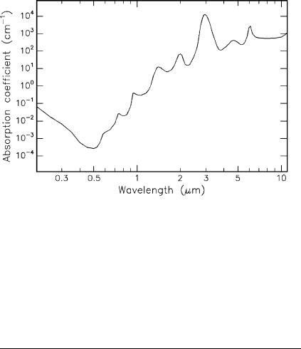
In biological tissue, absorption is mainly due to the presence of free water molecules, proteins, pigments, and other macromolecules as discussed in Sect. 2.3. It is governed by Lambert’s law which we already encountered in (2.13). The absorption coe cient strongly depends on the wavelength of the incident laser radiation. In thermal interactions, absorption by water molecules plays a significant role. Therefore, the absorption spectrum of water – one important constituent of most tissues – is plotted in Fig. 3.14. In the visible range, the absorption coe cient of water is extremely small. In this section of the spectrum and in the UV, absorption in tissue is higher than shown in Fig. 3.14, depending on the relative content of macromolecules such as melanin and hemoglobin. Toward the IR range of the spectrum, however,
3.2 Thermal Interaction |
65 |
Fig. 3.14. Absorption of water. Data calculated from Hale and Querry (1973)
water molecules are the dominant absorbers, since their absorption coe cient then increases by several orders of magnitude. Typical absorption coe cients α and the corresponding absorption lengths L for the most important laser wavelengths are summarized in Table 3.3. It should be borne in mind that the total attenuation in the UV is strongly enhanced by Rayleigh scattering as discussed in Sect. 2.3.
Table 3.3. Absorption coe cients α and absorption lengths L of water at di erent wavelengths. Data calculated from Hale and Querry (1973)
Wavelength (nm) |
Laser type |
α (cm−1) |
L (cm) |
193 |
ArF |
0.1 |
10 |
248 |
KrF |
0.018 |
55 |
308 |
XeCl |
0.0058 |
170 |
351 |
XeF |
0.0023 |
430 |
514 |
Argon ion |
0.00029 |
3400 |
633 |
He-Ne |
0.0029 |
340 |
694 |
Ruby |
0.0056 |
180 |
800 |
Diode |
0.020 |
50 |
1053 |
Nd:YLF |
0.57 |
1.7 |
1064 |
Nd:YAG |
0.61 |
1.6 |
2120 |
Ho:YAG |
36 |
0.028 |
2940 |
Er:YAG |
12000 |
0.00008 |
10600 |
CO2 |
860 |
0.001 |
|
|
|
|
66 3. Interaction Mechanisms
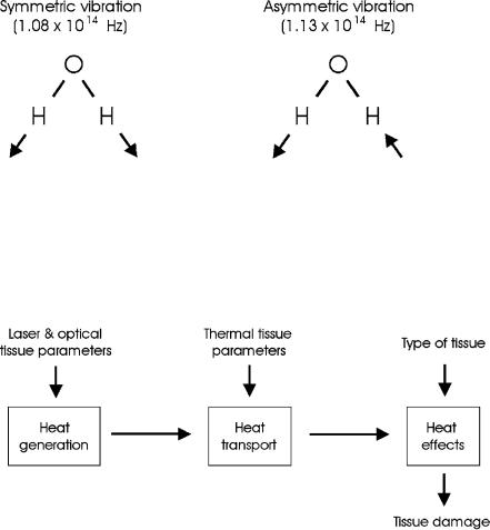
The absorption peak at about 3μm – as shown in Fig. 3.14 – is of considerable interest. It originates from symmetric and asymmetric vibrational modes of water molecules as illustrated in Fig. 3.15. According to Pohl (1976), the resonance frequencies of these vibrational modes are 1.08 × 10¹⁴ Hz and 1.13×10¹⁴ Hz, respectively. These correspond to a wavelength close to 3μm, thereby explaining the high absorption peak at this wavelength. Thus, the family of Er3+ doped lasers (Er:YAG at 2.94μm, Er:YLF at 2.8μm, and Er:YSGG at 2.79μm) is a typical representative of thermally acting lasers. A similar argument applies for the wavelength of the Ho:YAG laser at 2.12μm which also matches an absorption peak of water.
Fig. 3.15. Vibrational oscillations of water molecules
So far, we have encountered the basic origins of thermal e ects, and we will now proceed to setting up a model explaining the basic physics involved. In order to derive a model which describes thermal e ects quantitatively, several input parameters have to be taken into account. They are summarized in a flow chart as shown in Fig. 3.16.
Fig. 3.16. Flow chart with important parameters for modeling thermal interaction
3.2 Thermal Interaction |
67 |
Heat generation is determined by laser parameters and optical tissue properties – primarily irradiance, exposure time, and the absorption coe cient – with the absorption coe cient itself being a function of the laser wavelength. Heat transport is solely characterized by thermal tissue properties such as heat conductivity and heat capacity. Heat e ects, finally, depend on the type of tissue and the temperature achieved inside the tissue.
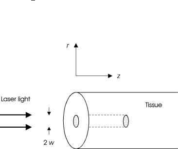
We assume that a slab of tissue is exposed in air to a Gaussian-shaped laser beam as illustrated in Fig. 3.17. For the sake of simplicity, a cylindrical geometry is chosen with z denoting the optical axis, and r the distance from this axis. Then, the amplitude of the electric field and the corresponding
intensity inside the tissue are given by |
|
|
|
|
|
|
||||||
E(r,z,t) = E0 exp − |
r2 |
αz |
2 |
|
|
|||||||
|
− |
|
|
exp − |
4t |
, |
(3.1) |
|||||
w2 |
2 |
|
τ2 |
|||||||||
I(r,z,t) = I0 exp − |
2r2 |
−αz exp − |
8t2 |
|
, |
(3.2) |
||||||
w2 |
τ2 |
|||||||||||
where E0 and I0 are the incident values of electric field and intensity, respectively, w is the beam waist, α is the absorption coe cient, and τ is the pulse duration. From (3.2), we obtain that either at r = w or at t = τ/2 the intensity is cut down to 1/e2 of its incident value. The incident values E0 and I0 are related to each other by the basic electrodynamic equation
I0 = 12 ε0cE20 ,
where ε0 is the dielectric constant, and c is the speed of light. Scattering inside the tissue is neglected in a first approximation. Calculations taking scattering e ects into account will be found at the end of this section.
Fig. 3.17. Geometry of tissue irradiation