

Kluwer - Handbook of Biomedical Image Analysis Vol
.1.pdf164 |
Rakesh Sharma and Avdhesh Sharma |
a result of the reduced saturation dependency, short TR of 25–28 msec is used with the minimal saturation of moving spins. It allows the spins to recover from previous RF pulses. Longitudinal recovery occurs exponentially with a time constant T1. Normally, repitition time TR five times the value of T1 is needed to ensure complete relaxation. However, long TR would limit the amount of data acquired and make 3D imaging difficult. Full relaxation can be achieved with a short pulse delay if smaller flip angles are used. Partially relaxed steady states are easily achieved with shorter pulse delays using the limited flip angles, the so-called gradient-recalled acquisition in the steady state for 2D or 3D volume acquisitions. Further reductions in saturation effects may also be realized by using intravenous contrast agents that shorten the T1 of blood. These refer to the gradual loss of longitudinal magnetization caused by repeated excitation RF pulses. This leads to loss of signal-to-noise ratio during 2D acquisition in which flowing blood has to travel within a slice or in a 3D acquisition in which the blood travels through a thick imaging volume (or slab). In such a situation, saturation effects may prevent the imaging of the distal portion of a vessel.
Contrast mechanism for vessel imaging is based on the differences in saturation between blood and stationary tissue, rather than flow itself. This contrast mechanism is usually dominated by “in flow” effects. TOF techniques differentiate blood only when its magnetization differs from that of surrounding stationary tissue. Longer blood stay in the imaging volume makes it more difficult to detect the vessels. Signal loss therefore occurs whenever slowly moving blood enters the volume of interest and reaches a new saturated steady state. Phase contrast angiography is less susceptible to this problem of signal loss. This may be due to saturation effects arising out of decreased TR and increased α factor.
Let us describe these factors.
3.2.6.2.1 Short TR. Short repetition times (TR) cause less recovery of longitudinal magnetization from one cycle to the next, causing gradual loss of the
Mz component. This effect is less pronounced with longer repetition times.
3.2.6.2.2 Larger Flip Angle (α). A large flip angle causes more signal loss due to loss of longitudinal magnetization. Therefore, for a given TR, there is greater gradual loss of Mz with a larger flip angle (α) than with a smaller flip angle (see Fig. 3.24). In GRE, very short TR is selected, as a result saturation effects pose a problem. The uses of small flip angles counteract this effect. These saturation effects become especially important in 2D and 3D-plane flow or in
Advances in Magnetic Resonance Angiography |
165 |
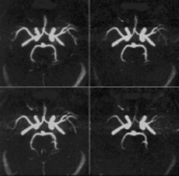
Figure 3.24: The figure represents the method of reformatting of TOF-MRA images by MIP. The technique generates the 3D images of blood vessels with blood motion. Larger flip angle at given TR show loss of magnetization and generate the different 3D appearance of vasculature (shown on right panel at bottom).
3D imaging in which volume imaging is performed over an imaging slab. Signal losses might be significant from one end of the slab to the other end of the slab.
3.2.7 Multislice GRE Techniques
These techniques use longer decrease in repetition time TR. As a result, the saturation effects lead to signal loss with the use of larger flip angles. This approach using longer decrease in TR improves the SNR. Other ways are also used to decrease saturation effects. Common use of paramagnetic contrast agent such as gadolinium chelate causes spin-lattice relaxation time (T1) shortening of blood (see Fig. 3.25). Consequently, the T1 recovery (from short T1 to normal T1 values) is faster with less saturation effects. In routine, multiple overlapping thin-slab acquisition (MOTSA) tilt optimized nonsaturated excitation (TONE) are also promising techniques to reduce saturation effects.

166 |
Rakesh Sharma and Avdhesh Sharma |
Figure 3.25: A method of multislice gradient echo is represented using short TR and larger flip angles with sufficient SNR (on left panel). However, gadolinium contrast agent shortened the blood with T1 recovery with less saturation effects (on right panel).
3.2.7.1 Multiple Overlapping Thin-Slab Acquisition (MOTSA)
It is a combination of 2D TOF and 3D TOF techniques for the purpose of reducing the saturation effects associated with a thick slab. In this method, multiple thin slabs used, which overlap by 25–50%. Extracting the central slices of each slab creates the final imaging volume and discards the peripheral slices, which are more affected by saturation effects. The main drawback of this technique is the appearance of “Venetian blind” artifact at the points where the slabs overlap.
3.2.7.2 Tilt Optimized Nonsaturated Excitation (TONE)
In this technique, flip angle (α) is increased progressively as the flowing spins move into the imaging volume by using increasing RF pulses. A large flip angle (α) yields higher SNR. Thus, larger flip angle counteracts the saturation effects of slow-flowing blood in deeper slices. This allows better visualization of distal vessels and the slow-flowing vessels. In common practice, ramped flip angle excitation pulse is used. In our commonly used scheme, the center flip angle is 30◦ and the flip angle at each end varies by 30%. As a result, flip angle changes 20◦ at the entry slice and 40◦ at the exit slice.
Advances in Magnetic Resonance Angiography |
167 |
3.2.8 Magnetization Transfer
This method is based on suppression of the off-resonant protein-bound water protons. If magnetization transfer (MT) is combined with TOF MRA, it helps suppress the background signal at least by 30%. The best-known example is brain parenchyma where MT-TOF MRA increases conspicuity of small and distal branches of vessels with slow flow, and aneurysms. MT can be combined with TONE for further visualization of small vessels.
3.2.9 Flow Eddies
The flow eddies are unique for identification and estimation of stenosis although these cause overestimation of stenosis by MRA. Flow eddies are mainly contributed by turbulent flow and vertex flow as well as stream separation distal to stenosis and carotid siphons (vessel turns). This overestimation of stenosis is the result of accelerated flow through the stenotic area leading to dephasing and flow void during TE. Common examples of overestimation are estimation of length of stenosis in the case of poststenosis or mimicking stenosis in the case of vessel turns.
3.2.10 Bright Blood Imaging
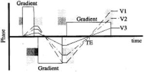
In addition to making the vessels appear black, vascular structures can also be visualized by making them brighter. Several techniques can be used to enhance the signal from flowing blood including gradient echo imaging and/or gradient moment rephasing and/or contrast enhancement. In gradient echo imaging, the flowing spins are refocused by the rephasing gradient. The patent vessels appear brighter on the images. This technique can be referred to as “bright blood imaging” and can be further improved by the application of an imaging option known as “gradient moment rephasing.” It is a first-order velocity compensation technique to visualize slow moving protons with constant velocity (see Fig. 3.26). Protons in venous blood or CSF are put into phase with the stationary protons. So, the intravoxel dephasing is reduced. Gradient moment rephasing compensates the flow by making these vessels containing slow flowing spins appear brighter. It enhances the signal from blood and CSF.
168 |
Rakesh Sharma and Avdhesh Sharma |
Figure 3.26: V1, V2, and V3 effect.
3.2.11 Black Blood MRA
Black blood MRA is another technique for MRA in which flowing blood appears dark rather than bright. It appears as negative of bright blood MRA. Rapidly flowing blood in arteries exhibits the TOF MRA signal losses. Slow flowing blood in veins appears as higher signal intensity. Various flow presaturation pulses and dephasing methods via gradients are employed in this technique to render flowing blood as black. This technique uses the MIP algorithm. Black blood MRA has several advantages. They offer no overestimation for the degree of stenosis and no dephasing in vessel turns that mimic stenosis. On the other hand, the technique has disadvantages that calcified plaque appears dark. Thus, this technique may underestimate the degree of stenosis or invisible plaques. Other black materials such as air or bone may mimic the blood flow.
Black blood MR angiograms make use of another time-of-flight phenomenon—the signal void observed for flowing blood in spin echo images. Unlike white blood, or INFLOW angiograms, which use a gradient echo sequence to enhance flowing blood and saturate static tissue, black blood angiography uses a spin echo sequence with presaturation to increase the signal of the tissue and to create a signal void (i.e. no MR signal) for flowing blood. The data is then processed using an MIP algorithm to yield the final MR angiogram. Black blood magnetic resonance angiography offers the advantage that signal voids due to turbulent flow are avoided. However, the contrast between vessel and static tissue may be lower, arterial and venous flow cannot be easily distinguished, and several regions of signal void such as nasal sinuses exist on images. Despite these disadvantages, black blood MRA may prove useful in the determination of some pathologies, such as severe stenotic lesions.
Advances in Magnetic Resonance Angiography |
169 |
3.3 Acquisition Methods
This section describes the basic theory of MR angiography, mainly the INFLOW, FLAG, and rapid sequential excitation (RSE) methods.
3.3.1 INFLOW Method—Time of Flight
This method belongs to a class of MR angiographic techniques known as “time- of-flight.” This technique gives rise to 3D information about the vessels in the volume of tissue being imaged with high contrast between the stationary tissue and the flowing blood. The INFLOW method relies on the flow related image enhancement caused by the movement of fresh, unsaturated blood into an already saturated slab of tissue. The INFLOW method has a number of advantages over other angiographic imaging methods. First, image subtraction is not necessary, thereby reducing scan time and computing requirements while speeding data manipulation. Second, high contrast can be obtained virtually independent of flow velocity. Third, the arteries or veins may be selectively imaged by the use of presaturation slabs. Finally, the technique does not require the use of selfshielded gradients. It is less sensitive to motion than the phase contrast methods. Using the INFLOW technique, angiograms may be obtained in only 10–15 min. For example, the data can be processed by sending a batch job or processed interactively with AP500 within 10 min. The choices are available on selecting INFLOW processing under the ANPROC key. Both batch and interactive processing are discussed later in this section.
To achieve the best possible contrast in the final images, the imaging parameters must provide for maximum refreshment of blood in the imaging volume. The threshold minimum velocity (Vt) is given by:
Vt = d/TR, |
(3.16) |
where d is the slice thickness and TR is the repetition time. For a typical 2D INFLOW sequence with 2 mm slices and TR = 50 ms, threshold velocity (Vt) will be 0.04 m/sec. For velocities greater than Vt, the signal intensity is essentially independent of the flow velocity. Typical velocities range from 1 m/sec for the aorta and 0.8 m/sec in the carotid artery and 0.03 m/sec in small veins.

170 |
Rakesh Sharma and Avdhesh Sharma |
Figure 3.27: Partition effect.
The phase of the transverse magnetization is made independent of the flow velocity by the use of velocity compensated gradients. However, higher order flow terms may cause signal void in the areas of turbulent flow. The use of short echo times compensates for this. If the stationary tissue is selected as the volume of interest, it may be saturated using a short TR and a large tip angle (see Fig. 3.27). During this pulse sequence, fresh unsaturated blood moves into the imaging slice. This results in good contrast between the unsaturated blood and the stationary tissue.
The INFLOW technique may be used with 2D multiple single slice or 3D acquisition with a flow compensated gradient echo sequence. For 2D multiple- single-slice INFLOW, many thin (2–3 mm) contiguous (or over contiguous) slices are collected in a plane that is orthogonal to the blood flow. The optimum contrast between flowing blood and stationary tissue should be obtained with the shortest TE, a TR of the order of 40–60 msec, and a large tip angle of 45–90◦, depending on the anatomy being studied and the flow rate of blood. Presaturation of a slab above or below the imaging slice allows selective imaging of the veins or arteries. The single sided, parallel presaturation slab moves with the slice position, ensuring good suppression. The slab thickness is adjusted in the second pass parameters and is typically set to 50 mm. An alternative method for certain imaging protocols employs a presaturation plane that is perpendicular to the imaging slice. An example is the use of a sagittal or coronal slice for imaging the carotid arteries. A perpendicular presaturation slab is necessary to remove the venous flow.
Advances in Magnetic Resonance Angiography |
171 |
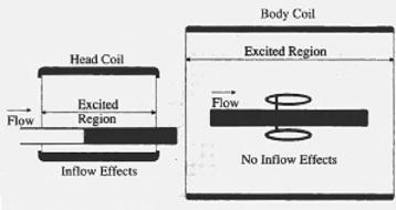
Figure 3.28: Excitation in coil.
Since the 2D method is a multiple-single-slice technique, the slices are reconstructed as they are collected. They may be viewed while subsequent slices are being collected. This feature allows the operator to monitor the data collection. Later, data collection may be stopped to correct the protocol, if necessary, without waiting for all the data to be collected. It also shortens the study time by reconstructing the slices while the acquisition is still in progress. In our experience for routine transverse slices of the carotids, processing methods consist of projecting the stack of slices in a plane orthogonal axis. Top–down projections or perpendicular projections in the AP direction may be generated with appropriate selection of projections in the select procedure menu (see Fig. 3.28). First projection will be generated when slices are reconstructed. INFLOW image processing uses a maximum intensity projection with the interpolation between the slices. The maximum intensity voxel in a given vector is used for that projection view.
3.3.2 FLAG, RSE-Phase Contrast
Flow adjusted gradient (FLAG) and RSE are fast field echo sequences. They have velocity-sensitive gradients that are designed to image flow by adjusting their sensitivities to different flow velocities. The contrast between flowing and stationary tissue is based on the phase of the transverse magnetization of moving spins rather than on time-of-flight effects. Spins moving in the presence of a magnetic gradient accumulate a flow-induced phase shift. This phase shift depends on the strength and duration of the gradient and the velocity of the moving spins.
172 |
Rakesh Sharma and Avdhesh Sharma |
In our experience, two or more images are collected, one of which is velocity sensitive in a specified direction and the other is velocity compensated image. For example, a thick slab (100 mm) FLAG sequence in the plane of flow (thick coronal slab for imaging the abdominal aorta) will yield a projective MR angiographic image. The resultant phase images are phase corrected and subtracted to yield the projection angiogram. The FLAG sequence can be run with or without cardiac triggering. In the noncardiac triggered version, a “shortest” TR is not recommended. The FLAG sequence interleaves the velocity compensated and velocity-sensitive data in consecutive TR periods. If the scan is gated, FLAG sequence interleaves the velocity sensitive data such as in consecutive heartbeats. For better suppression of respiratory motion, the RSE sequence may be used. RSE interleaves the velocity compensated and velocity-sensitive data in the same heartbeat. The RSE sequence must be run in the cardiac triggered mode.
3.3.3 Digital Subtraction MRA
Digital subtraction MRA has been compared to digital subtraction angiography (DSA) as contrast is selectively produced for moving spins during two acquisitions. These moving spins are then subtracted to remove the signal from the stationary spins, leaving behind an image of the moving spins. An early subtraction angiogram may be performed while gating to the cardiac cycle. An acquisition during systole (fast flow) is generally subtracted from an acquisition during dystole (slow flow). In this case, the stationary spins were subtracted, retaining only the moving spins, such as the vasculature, on the resultant image. This technique is significant as recent techniques were based on same principles.
3.4 Recent Advancement in MRA Techniques
Different newer methods are reported in the literature for MRA from the perspective of different applications applied for flow imaging.
3.4.1 Sensitivity Encoding
Sensitivity encoding (SENSE) is used to increase spatial resolution and decrease venous contamination in peripheral MRA. In this method, single-bolus peripheral
Advances in Magnetic Resonance Angiography |
173 |
contrast-enhanced (CE)-MRA was performed [1]. Manual table movements combined with SENSE in the upper station allowed for more rapid overall scan coverage such that acquisition of the lower station began 34 sec after aortic contrast arrival. True submillimeter isotropic resolution was achieved in the lower station. Diagnostic MR angiograms of all three stations were obtained. Venous enhancement did not confound interpretation in any case. Submillimeter lower station resolution provided excellent vascular details. Decreased delay time between upper and lower station acquisition in single-bolus peripheral MR angiograms, now possible using parallel imaging techniques, combined with lower station submillimeter resolution, may decrease venous contamination and increase overall interpretability, thus increasing clinical acceptance of peripheral MRA.
3.4.2 Blood Pool Contrast Enhancement
This technique of blood pool contrast-enhanced MRA was used to visualize the arterial and venous vessel tree and to detect deep venous thrombosis of the lower extremities. Patients with pulmonary embolism were randomized to evaluate various doses of NC100150 by T1-weighted (T1W) 3D gradient recalled echo sequence. Qualitative assessment of overall MRA image quality and semiquantitative vessel scoring revealed good to excellent delineation of venous and arterial vessel segments independent of the dose of NC100150. However, quantitative region of interest analysis revealed a significantly higher signal-to-noise ratio in the high-dose group than in the midand low-dose groups of NC100150. Between dose groups, the SNR was independent of vessel type (artery or vein) and vessel segment localization (proximal or distal). Venous thrombi were characterized by very low signal intensity, approximately one tenth the SI in adjacent venous segments. High-quality MR angiograms of the lower extremities can be obtained using low concentrations of NC100150 in combination with a strong T1W 3D GRE sequence. The obvious delineation of venous thrombi suggests that this technique may be potentially used as a noninvasive “one-stop shopping” tool in the evaluation of thrombo-embolic disease [2].
3.4.3 Digital Subtraction Angiography
Contrast-magnetic resonance angiography (CE-MRA) MoBI-trak was used in the evaluation of the peripheral vessels in patients with peripheral vascular