

Whats A Microcontroller v3
.0.pdfControlling Motion · Page 101
9Connect the servo to the servo header as shown in Figure 4-11.
9Make sure that the colors on the servo’s cable align properly with the colors labeled in the picture.
9Double-check your wiring.
WARNING
Use only a 9 V battery when your Parallax Standard Servo is connected to the BASIC Stamp HomeWork Board. Do not use any kind of DC supply or “battery replacer” that plugs into an AC outlet.
For best results, make sure your battery is new. If you are using a rechargeable battery, make sure it is freshly recharged. It should also be rated for 100 mAh (milliamp hours) or more.
9Reconnect your 9 V battery to your HomeWork Board. The servo may twitch slightly when you make the connection.
Figure 4-11
Servo Connected to
HomeWork Board

Page 102 · What’s a Microcontroller?
ACTIVITY #2: SERVO CONTROL TEST PROGRAM
A degree is an angle measurement denoted by the ° symbol. Example degree angle measurements are shown in Figure 4-12, including 30°, 45°, 90°, 135°, and 180°. Each degree of angle measurement represents 1/360th of a circle, so the 90° measurement is ¼ of a circle since 90 ÷ 360 = ¼. Likewise, 180° is ½ of a circle since 180 ÷ 360 = ½, and you can calculate similar fractions for the other degree measurements in the figure.
Figure 4-12
Examples of
Degree Angle
Measurements
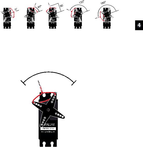
The Parallax Standard Servo can make its horn hold positions anywhere within a 180° range, so degree measurements can be useful for describing the positions the servo holds. Figure 4-13 shows examples of a servo with a loop of wire that has been threaded through two of the holes in its horn and then twist-tied. The direction the twist tie points indicates the angle of the servo’s horn, and the figure shows examples of 0°, 45°, 90°, 135°, and 180°.
Figure 4-13: Servo Horn Position Examples
Your servo horn’s range of motion and mechanical limits will probably be different from what’s shown here. Instructions on how to adjust it to match this figure come after the first example program.
Factory servo horn mounting is random, so your servo horn positions will probably be different from the ones in Figure 4-13. In fact, compared to Figure 4-13, your servo’s horn could be mounted anywhere in a +/- 45° range. The servo in Figure 4-14 shows an example of a servo whose horn was mounted 20° clockwise from the one in Figure 4-13. After you find the center of the servo horn’s range of motion, you can either use it as a 90° reference or mechanically adjust the servo’s horn so that it matches Figure 4-13 by following instructions later in this activity.
Controlling Motion · Page 103
Figure 4-14: Servo Horn Position Examples before Mechanical Adjustment
This is an example of a horn that’s mounted on the servo’s output shaft about 20° counterclockwise of how it was set in Figure 4-13.
You can find the center of the servo’s range of motion by gently rotating the horn to find its clockwise and counterclockwise mechanical limits. The half way position between these two limits is the center or 90° position. The servo’s center position could fall anywhere in the region shown in Figure 4-15.
The center of your servo horn’s range of motion should fall somewhere in this region
Figure 4-15
Range of Possible
Center Positions

Page 104 · What’s a Microcontroller?
In these next steps, twist the servo horn slowly and do not force it! The servo has built-in mechanical limits to prevent the horn from rotating outside its 180° range of motion. Twist the horn gently, and you’ll be able to feel the when it reaches one of its mechanical limits. Don’t try to force it beyond those limits because it could strip the gears inside the servo.
9Verify that the power to your board is still disconnected.
9Gently rotate the servo horn to find the servo’s clockwise and counterclockwise mechanical limits. The servos horn will turn with very little twisting force until you reach these limits. DO NOT TRY TO TWIST THE HORN PAST THESE LIMITS; only twist it far enough to find them.
9Rotate the servo’s horn so that it is half way between the two limits. This is approximately the servo’s “center” position.
9With the servo horn in its center position, thread a jumper wire through the horn and twist tie it so that it points upward into the region shown in Figure 4-15.
Keep in mind the direction the twist tie is pointing in the figure is just an example; your twist tie might point anywhere in the region. Wherever it points when it’s in the center of its range of motion should be pretty close to the servo’s 90° position. Again, this position can vary from one servo to the next because of the way the horn gets attached to the servo.
Programming Servo Positions
The graph in Figure 4-16 is called a timing diagram, and it shows examples of the high/low signals the BASIC Stamp has to send a servo to make it hold its 90° position.
Figure 4-16
Servo Signal Timing
Diagram
1.5 ms pulses make the servo hold a 90° “center” position.
The timing diagram shows high signals that last for 1.5 ms, separated by low signals that last 20 ms. The ... to the right of the signal is a way of indicating that the 1.5 ms high and 20 ms low signal has to be repeated over and over again to make the servo hold the

Controlling Motion · Page 105
position. The “~” symbol in “~20 ms” indicates that the low time can be approximate, and it can actually vary a few milliseconds above or below 20 ms with next to no effect on the where the servo positions its horn. That’s because amount of time the high signal lasts is what tells the servo what position to hold, so it has to be precise.
There’s a special command called PULSOUT that gives your program precise control over the durations of those very brief high signals, which are commonly referred to as pulses. Here is the command syntax for PULSOUT:
PULSOUT Pin, Duration
With the PULSOUT command, you can write PBASIC code to make the BASIC Stamp set the servo’s position to 90° using the Figure 4-16 timing diagram as a guide. The PULSOUT command’s Pin argument has to be a number that tells the BASIC Stamp which I/O pin should transmit the pulse. The PULSOUT command’s Duration argument is the number of 2-millionths-of-a-second time increments the pulse should last. 2 millionths of a second is equal to 2 microseconds, which is abbreviated 2 μs.
A millionth of a second is called a microsecond. The Greek letter μ is used in place of the word micro and the letter s is used in place of second. This is handy for writing and taking notes, because instead of writing 2 microseconds, you can write 2 μs.
Reminder: one thousandth of a second is called a millisecond, and is abbreviated ms.
Fact: 1 ms = 1000 μs. In other words, you can fit one thousand millionths of a second into one thousandth of a second.
Now that we know how to use the PULSOUT command, ServoCenter.bs2 sends control pulses repeatedly to make the servo hold its 90° position. The command PULSOUT 14, 750 will send a 1.5 ms pulse to the servo. That’s because the PULSOUT command’s Duration argument specifies the number of 2 μs units the pulse should last. Since the Duration argument is 750, the PULSOUT command will make the pulse last for 750 × 2 μs = 1500 μs, which is 1.5 ms since there are 1000 μs in 1 ms. After the high pulse is done, the PULSOUT command leaves the I/O pin sending a low signal. So, a PAUSE 20 command after PULSOUT makes the BASIC Stamp send a low signal for 20 ms. With both of those commands inside a DO...LOOP, the 1.5 ms high followed by the 20 ms low will repeat over and over again to make the servo hold its position.

Page 106 · What’s a Microcontroller?
Example Program: ServoCenter.bs2
'What's a Microcontroller - ServoCenter.bs2
'Hold the servo in its 90 degree center position.
'{$STAMP BS2}
'{$PBASIC 2.5}
DEBUG "Program Running!", CR
DO
PULSOUT 14, 750
PAUSE 20
LOOP
Test the Servo’s 90° “Center” Position
The servo’s 90° position is called its center position because the 90° point is in the “center” of the servo’s 180° range of motion. The 1.5 ms pulses make the servo hold its horn in this center position, which should be close to the half way point you determined by finding the servo’s mechanical limits. You can either use whatever center position the servo holds as your reference for 90°, or use a screwdriver to remove and reposition the horn so that 90° makes the jumper wire twist tie point straight up. Instructions for this are coming up in the section titled: Optional – Adjust Servo Horn to 90° Center. If you use the center position as a reference without adjusting it, any other position the servo holds will be relative that 90° position. For instance, the 45° position would be 1/8 of a turn clockwise from it, and the 135° position would be 1/8 of a turn counterclockwise. Examples of this were shown in Figure 4-14 on page 103.
Let’s first find what your servo’s actual center position is:
9Gently turn the servo’s horn to one of its mechanical limits.
9Reconnect power to your board. If you have a Board of Education, make sure to slide the 3-position all the way to the right (to position-2).
9Run ServoCenter.bs2.
As soon as the program loads, the servo’s horn should rotate to its center position and stay there. The servo “holds” this position, because standard servos are designed to resist external forces that push against it. That’s how the servo holds the RC car steering, boat rudder, or airplane control flap in place.
9 Make a note of your servo’s center position.

Controlling Motion · Page 107
9Apply gentle twisting pressure to the horn like you did while rotating the servo to find its mechanical limits. The servo should resist and hold its horn in its center position.
If you disconnect power, you can rotate the servo away from its center position. When you reconnect power, the program will restart, and servo will immediately move the horn back to its center position and hold it there.
9 Try it!
Optional – Adjust Servo Horn to 90° Center
You can optionally adjust your servo’s horn so that it makes the jumper wire twist tie point straight up when ServoCenter.bs2 is running, like it does in the right side of Figure 4-17. If you make this mechanical adjustment, it’ll simplify tracking the servo’s angles because each angle will resemble the ones in Figure 4-13 on page 102.
You will need a #2 Phillips screwdriver for this optional adjustment.
Output |
|
|
shaft |
Phillips |
Figure 4-17 |
|
||
|
Screw |
Mechanical Servo |
|
|
|
|
|
Centering |
You can remove and reposition the servo horn on the output shaft with a small screwdriver.
Horn
9 Disconnect power from your board.

Page 108 · What’s a Microcontroller?
9Remove the screw that attaches the servo’s horn to its output shaft, and then gently pull the horn away from case to free it. Your parts should resemble the left side of Figure 4-17.
9Reconnect power to your board. The program should make the servo hold its output shaft in the center position.
9Slip the horn back onto the servo’s output shaft so that it makes the twist tied wire point straight up like it does on the right side of Figure 4-17.
Alignment Offset: It might not be possible to get it to line up perfectly because of the way the horn fits onto the output shaft, but it should be close. You can then adjust the wire loop to compensate for this small offset and make the twist tie point straight up.
9Disconnect power from your board.
9Retighten the Phillips screw.
9Reconnect power so that the program makes the servo hold its center position again. The twist tie should now point straight up (or almost straight up) indicating the 90° position.
Your Turn – Programs to Point the Servo in Different Directions
Figure 4-18 shows a few PULSOUT commands that tell the servo to hold certain major positions, like 0°, 45°, 90°, 135°, and 180°. These PULSOUT commands are approximate, and you may have to adjust the values slightly to get more precise angular positions. You can modify the PULSOUT command’s Duration argument to hold any position in this range. For example, if you want the servo to hold the 30° position, your PULSOUT command’s Duration argument would have to be 417, which is 2/3 of the way between Duration arguments of 250 (0°) to 500 (45°).
The pulse durations in Figure 4-18 will get the servo horn close to the angles shown, but they are not necessarily exact. You can experiment with different PULSOUT Duration values for more precise positioning.
9Save a copy of ServoCenter.bs2 as TestServoPositions.bs2
9Change the program’s PULSOUT Duration argument from 750 to 500, and run the modified program to verify that it makes the servo hold its 45° position.
9Repeat this test of PULSOUT Duration arguments with 1000 (135°), and 417 (30°).

Controlling Motion · Page 109
9Try predicting a PULSOUT Duration you would need for a position that’s not listed in Figure 4-18, and test to make sure the servo turns the horn to and holds the position you want. Example positions could include 60°, 120°, etc.
Keep your program’s PULSOUT Duration arguments in the 350 to 1150 range. The 250 to 1250 range is “in theory” but in practice the servo might try to push against its mechanical limits. This can reduce the servo’s useful life. If you want to maximize your servo’s range of motion, carefully test values that get gradually closer to the mechanical limits. So long as you use PULSOUT Duration values that cause the servo to position its horn just inside its mechanical limits, wear and tear will be normal instead of excessive.
Figure 4-18: Servo Horn Positions, PULSOUT Commands, and ms Pulse Durations

Page 110 · What’s a Microcontroller?
Do the Math
Along with each PULSOUT command in Figure 4-18, there’s a corresponding number of milliseconds that each pulse lasts. For example, the pulse that PULSOUT 14, 417 sends lasts 0.834 ms, and the pulse that PULSOUT 14, 500 sends lasts 1.0 ms. If you have a BASIC Stamp 2 and want to convert time from milliseconds to a Duration for your PULSOUT command, use this equation:
Duration = number of ms ×500
For example, if you didn’t already know that the PULSOUT Duration argument for 1.5 ms is 750, here is how you could calculate it:
Duration =1.5 ×500
= 750
The reason we have to multiply the number of milliseconds in a pulse by 500 to get a PULSOUT Duration argument is because Duration is in terms of 2 μs units for a BS2. How many 2 μs units are in 1 ms? Just divide 2-one-millionths into 1-one-thousandth to find out.
1 |
÷ |
2 |
= 500 |
|
1,000 |
1,000,000 |
|||
|
|
If your command is PULSOUT 14, 500, the pulse will last for 500 × 2 μs = 1000 μs = 1.0 ms. (Remember, 1000 μs = 1 ms.)
You can also figure out the Duration of a mystery PULSOUT command using this equation:
number of ms = Duration500 ms
For example, if you see the command PULSOUT 14, 850, how long does that pulse really last?
number of ms = 850500 ms
=1.7 ms