

Whats A Microcontroller v3
.0.pdfMeasuring Rotation · Page 141
ACTIVITY #1: BUILDING AND TESTING THE POTENTIOMETER CIRCUIT
Placing different size resistors in series with an LED causes different amounts of current to flow through the circuit. Large resistance in the LED circuit causes small amounts of current to flow through the circuit, and the LED glows dimly. Small resistances in the LED circuit causes more current to flow through the circuit, and the LED glows more brightly. By connecting the W and A terminals of the potentiometer, in series with an LED circuit, you can use it to adjust the resistance in the circuit. This in turn adjusts the brightness of the LED. In this activity, you will use the potentiometer as a variable resistor and use it to change the brightness of the LED.
Dial Circuit Parts
(1) Potentiometer – 10 kΩ
(1) Resistor – 220 Ω (red-red-brown)
(1) LED – red
(1) Jumper wire
Building the Potentiometer Test Circuit
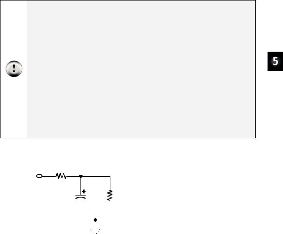
Figure 5-5 shows a circuit that can be used for adjusting the LED’s brightness with a potentiometer.
9 Build the circuit shown in Figure 5-5.
Tip: If you have trouble keeping the potentiometer seated in the breadboard sockets, check its legs. If each one has a small bend, use a needle-nose pliers to straighten them out and then try plugging the pot into the breadboard again. When the pot’s legs are straight, they may maintain better contact with the breadboard sockets.

Page 142 · What’s a Microcontroller?
Figure 5-5
Potentiometer-LED
Test Circuit
Testing the Potentiometer Circuit
9Turn the potentiometer clockwise until it reaches its mechanical limit shown in Figure 5-6 (a).
Press the pot against the breadboard a little as you turn its knob. For these activities, the potentiometer needs to be firmly seated in the breadboard sockets. If you’re not careful when you turn the knob, the pot can become disconnected from the breadboard sockets, and that can lead to incorrect measurements. So, apply a little downward pressure as you turn the potentiometer’s knob to keep it seated in the breadboard.
Handle with care: If your potentiometer will not turn this far, do not try to force it. Just turn it until it reaches its mechanical limit; otherwise, it might break.
9Gradually rotate the potentiometer counterclockwise to the positions shown in Figure 5-6 (b), (c), (d), (e), and (f) noting the how brightly the LED glows at each position.

Measuring Rotation · Page 143
|
|
|
Figure 5-6 |
(a) |
(c) |
(e) |
Potentiometer Knob |
|
|||
|
|
|
(a) through (f) show the |
(b) |
(d) |
(f) |
potentiometer’s wiper |
|
|
|
terminal set to different |
positions.
How the Potentiometer Circuit Works
The total resistance in your test circuit is 220 Ω plus the resistance between the A and W terminals of the potentiometer. The resistance between the A and W terminals increases as the knob is adjusted further clockwise, which in turn reduces the current through the LED, making it dimmer.
ACTIVITY #2: MEASURING RESISTANCE BY MEASURING TIME
This activity introduces a new part called a capacitor. A capacitor behaves like a rechargeable battery that only holds its charge for short durations of time. This activity also introduces RC-time, which is an abbreviation for resistor-capacitor time. RC-time is a measurement of how long it takes for a capacitor to lose a certain amount of its stored charge as it supplies current to a resistor. By measuring the time it takes for the capacitor to discharge with different size resistors and capacitors, you will become more familiar with RC-time. In this activity, you will program the BASIC Stamp to charge a capacitor and then measure the time it takes the capacitor to discharge through a resistor.
Introducing the Capacitor
Figure 5-7 shows the schematic symbol and part drawing for the type of capacitor used in this activity. Capacitance value is measured in microfarads (µF), and the measurement is typically printed on the capacitors.
The cylindrical case of this particular capacitor is called a canister. This type of capacitor, called an electrolytic capacitor, must be handled carefully.
9 Read the CAUTION box on the next page.

Page 144 · What’s a Microcontroller?
CAUTION: This capacitor has a positive (+) and a negative (-) terminal. The negative terminal is the lead that comes out of the metal canister closest to the stripe with a negative
(–) sign. Always make sure to connect these terminals as shown in the circuit diagrams. Connecting one of these capacitors incorrectly can damage it. In some circuits, connecting this type of capacitor incorrectly and then connecting power can cause it to rupture or even explode.
CAUTION: Do not apply more voltage to an electrolytic capacitor than it is rated to handle. The voltage rating is printed on the side of the canister.
CAUTION: Safety goggles or safety glasses are recommended.
3300 µF
3 3 0 0 µ F
+ -
-
Figure 5-7
3300 µF Capacitor Schematic
Symbol and Part Drawing
Pay careful attention to the leads and how they connect to the Positive and Negative Terminals.
Resistance and Time Circuit Parts
(1) Capacitor – 3300 µF
(1) Capacitor – 1000 µF
(1)Resistor – 220 Ω (red-red-brown)
(1)Resistor – 470 Ω (yellow-violet-brown)
(1)Resistor – 1 kΩ (brown-black-red)
(1)Resistor – 2 kΩ (red-black-red)
(1)Resistor – 10 kΩ (brown-black-orange)
Building and Testing the Resistor-Capacitor (RC) Time Circuit
Figure 5-8 shows the circuit schematic and Figure 5-9 shows the wiring diagram for this activity. You will be taking time measurements using different resistor values in place of the resistor labeled Ri.
Measuring Rotation · Page 145
9 Read the SAFETY box carefully.
SAFETY
Always observe polarity when connecting the 3300 or 1000 μF capacitor. Remember, the negative terminal is the lead that comes out of the metal canister closest to the stripe with a negative (–) sign. Use Figure 5-7 to identify the (+) and (-) terminals.
Your 3300 μF capacitor will work fine in this experiment so long as you make sure that the positive (+) and negative (-) terminals are connected EXACTLY as shown in Figure 5-8 and Figure 5-9.
Never reverse the supply polarity on the 3300 μF or any other polar capacitor. The voltage at the capacitor’s (+) terminal must always be higher than the voltage at its (-) terminal. Vss is the lowest voltage (0 V) on the Board of Education and BASIC Stamp HomeWork Board. By connecting the capacitor’s negative terminal to Vss, you ensure that the polarity across the capacitor’s terminals will always be correct.
Never apply voltage to the capacitor that exceeds the voltage rating on the canister. Wear safety goggles or safety glasses during this activity.
Always disconnect power before you build or modify circuits.
Keep your hands and face away from this capacitor when power is connected.
9With power disconnected, build the circuit as shown starting with a 470 Ω resistor in place of the resistor labeled Ri.
P7
220 Ω |
|
|
|
|
|
|
|
|
|
R1 |
= 470 Ω |
|
|
|
|
|
|
|
|
|
Ri |
||
3300 µF |
|
|
|
|
|
|
|
|
R2 |
= 1 kΩ |
|
|
|
|
|
|
|
|
|
|
|
R3 = 2 kΩ |
|
|
|
|
|
|
|
|
|
|
|
R4 = 10 kΩ |
|
|
|
|
|
|
|
|
|
|
|
|
|
|
|
|
|
|
|
|
|
|
|
|
|
|
|
|
|
|
|
|
|
||||
|
|
|
|
|
|
||||||
|
Vss |
|
|
||||||||
Figure 5-8
Schematic for Testing RC-time Voltage Decay
The four different resistors will be used one at a time as Ri in the schematic.
Four different resistors will be used as Ri shown in the schematic. First, the schematic will be built and tested with Ri = 470 Ω, and then Ri = 1 kΩ, etc. will be used later.

Page 146 · What’s a Microcontroller?
R4 |
R3 |
R2 |
R1 |
|
|
|
|
|
|
|
|
|
Vdd |
Vin |
Vss |
- |
|
|
|
|
F |
|
|
|
|
|
µ |
|||||
|
|
|
|
|
|
|
0 |
|
||
X3 |
|
|
|
|
|
0 |
|
|
||
|
|
|
|
|
3 |
|
|
|
||
|
|
|
|
|
|
3 |
|
|
|
|
P15 |
|
|
|
|
|
+ |
|
|
|
|
P14 |
|
|
|
|
+ |
|
|
|
|
|
P13 |
|
|
|
|
|
|
|
|
|
|
P12 |
|
|
|
|
|
|
|
|
|
|
P11 |
|
|
|
|
|
|
|
|
|
|
|
|
|
|
|
|
|
|
|
|
|
P10 |
|
|
|
|
|
|
|
|
|
|
P9 |
|
|
|
|
|
|
|
|
|
|
P8 |
|
|
|
|
|
|
|
|
|
|
P7 |
|
|
|
|
|
|
|
|
|
|
P6 |
|
|
|
|
|
|
|
|
|
|
P5 |
|
|
|
|
|
|
|
|
|
|
P4 |
|
|
|
|
|
|
|
|
|
|
P3 |
|
|
|
|
|
|
|
|
|
|
P2 |
|
|
|
|
|
|
|
|
|
|
P1 |
|
|
|
|
|
|
|
|
|
|
P0 |
|
|
|
|
|
|
|
|
|
|
X2 |
|
|
|
|
|
|
|
|
|
|
Figure 5-9
Wiring Diagram for Viewing RC-time Voltage Decay
Make sure that the negative lead of the capacitor is connected on your board the same way it is shown in this figure, with the negative lead connected to Vss.
9Make sure that the negative lead of the capacitor is connected on your board the same way it is shown in this figure, with the negative lead connected to Vss.
Polling the RC-Time Circuit with the BASIC Stamp
Although a stopwatch can be used to record how long it takes the capacitor’s charge to drop to a certain level, the BASIC Stamp can also be programmed to monitor the circuit and give you a more consistent time measurement.
Example Program: PolledRcTimer.bs2
9Enter and run PolledRcTimer.bs2.
9Observe how the BASIC Stamp charges the capacitor and then measures the discharge time.
9Record the measured time (the capacitor’s discharge time) in the 470 Ω row of Table 5-1.
9Disconnect power from your Board of Education or BASIC Stamp HomeWork Board.
9Remove the 470 Ω resistor labeled Ri in Figure 5-8 and Figure 5-9 on page 146, and replace it with the 1 kΩ resistor.
9Reconnect power to your board.
9Record your next time measurement (for the 1 kΩ resistor).

Measuring Rotation · Page 147
9 Repeat these steps for each resistor value in Table 5-1.
Table 5-1: Resistance and RC-time for C = 3300 μF
Resistance (Ω) |
Measured Time (s) |
|
|
470
1k
2k 10 k
'What's a Microcontroller - PolledRcTimer.bs2
'Reaction timer program modified to track an RC-time voltage decay.
'{$STAMP BS2}
'{$PBASIC 2.5}
timeCounter |
VAR |
Word |
|
counter |
VAR |
Nib |
|
PAUSE |
1000 |
|
|
DEBUG |
CLS |
|
|
HIGH 7
DEBUG "Capacitor Charging...", CR
FOR counter = 5 TO 0
PAUSE 1000
DEBUG DEC2 counter, CR, CRSRUP
NEXT
DEBUG CR, CR, "Measure decay time now!", CR, CR
INPUT 7
DO
PAUSE 100
timeCounter = timeCounter + 1
DEBUG ? IN7
DEBUG DEC5 timeCounter, CR, CRSRUP, CRSRUP
LOOP UNTIL IN7 = 0
DEBUG CR, CR, CR, "The RC decay time was ", DEC timeCounter, CR,
"tenths of a second.", CR, CR
END
Page 148 · What’s a Microcontroller?
How PolledRcTimer.bs2 Works
Two variables are declared. The timeCounter variable is used to track how long it takes the capacitor to discharge through Ri. The counter variable is used to count down while the capacitor is charging.
timeCounter |
VAR |
Word |
counter |
VAR |
Nib |
The command DEBUG CLS clears the Debug Terminal so that it doesn’t get cluttered with successive measurements. HIGH 7 sets P7 high and starts charging the capacitor, then a “Capacitor charging…” message is displayed. After that, a FOR...NEXT loop counts down while the capacitor is charging. As the capacitor charges, the voltage across its terminals increases toward anywhere between 3.4 and 4.9 V (depending on the value of Ri).
DEBUG CLS
HIGH 7
DEBUG "Capacitor Charging...", CR
FOR counter = 5 TO 0
PAUSE 1000
DEBUG DEC2 counter, CR, CRSRUP
NEXT
A message announces when the decay starts getting polled.
DEBUG CR, CR, "Measure decay time now!", CR, CR
In order to let the capacitor discharge itself through the Ri resistor, the I/O pin is changed from HIGH to INPUT. As an input, the I/O pin, has no effect on the circuit, but it can sense high or low signals. As soon as the I/O pin releases the circuit, the capacitor discharges as it feeds current through the resistor. As the capacitor discharges, the voltage across its terminals gets lower and lower (decays).
INPUT 7
Back in the pushbutton chapter, you used the BASIC Stamp to detect a high or low signal using the variables IN3 and IN4. At that time, a high signal was considered Vdd, and a low signal was considered Vss. To the BASIC Stamp, actually a high signal is any voltage above about 1.4 V. Of course, it could be up to 5 V. Likewise, a low signal is

Measuring Rotation · Page 149
anything between 1.4 V and 0 V. This DO...LOOP checks P7 every 100 ms until the value of IN7 changes from 1 to 0, which indicates that the capacitor voltage decayed to 1.4 V.
DO
PAUSE 100
timeCounter = timeCounter + 1
DEBUG ? IN7
DEBUG DEC5 timeCounter, CR, CRSRUP, CRSRUP
LOOP UNTIL IN7 = 0
The result is then displayed and the program ends.
DEBUG CR, CR, CR, "The RC decay time was ",
DEC timeCounter, CR,
"tenths of a second.", CR, CR
END
Your Turn – A Faster Circuit
By using a capacitor that has roughly 1/3 the capacity to hold charge, the time measurement for each resistor value that is used in the circuit will be reduced by 1/3. Later on in the next activity, you will use a capacitor that has 1/33,000 the capacity! The BASIC Stamp will still take the time measurements for you, using a command called
RCTIME.
9Disconnect power to your Board of Education or HomeWork Board.
9Replace the 3300 µF capacitor with a 1000 µF capacitor.
9Confirm that the polarity of your capacitor is correct. The negative terminal should be connected to Vss.
9Reconnect power.
9Repeat the steps in the Example Program: PolledRcTimer.bs2 section, and record your time measurements in Table 5-2.
9Compare your time measurements to the ones you took earlier in Table 5-1. How close are they to 1/3 the value of the measurements taken with the 3300 µF capacitor?
Page 150 · What’s a Microcontroller?
Table 5-2: Resistance and RC-time for C = 1000 μF
Resistance (Ω) |
Measured Time (s) |
|
|
470
1k
2k 10 k
ACTIVITY #3: READING THE DIAL WITH THE BASIC STAMP
In Activity #1, a potentiometer was used as a variable resistor. The resistance in the circuit varied depending on the position of the potentiometer’s adjusting knob. In Activity #2, an RC-time circuit was used to measure different resistances. In this activity, you will build an RC-time circuit to read the potentiometer, and use the BASIC Stamp to take the time measurements. The capacitor you use will be very small, and the time measurements will be in the microseconds range. Even though the measurements take very short durations of time, the BASIC Stamp will give you an excellent indication of the resistance between the potentiometer’s A and W terminals which in turn indicates the knob’s position.
Parts for Reading RC-Time with the BASIC Stamp
(1) Potentiometer – 10 kΩ
(1)Resistor – 220 Ω (red-red-brown)
(2)Jumper wires
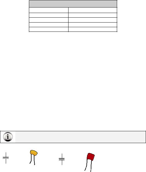
(1)Capacitor – 0.1 µF
(1)Capacitor – 0.01 µF
(2)Jumper wires
These capacitors do not have + and – terminals. They are non-polar. So, you can safely connect these capacitors to a circuit without worrying about positive and negative terminals.
|
1 |
|
04 |
0.1 µF |
0.01 µF |
|
1 |
0 |
|
3 |
Figure 5-10
Ceramic Capacitors
0.1 µF capacitor (left)
0.01 µF capacitor (right)