

Whats A Microcontroller v3
.0.pdfMeasuring Rotation · Page 151
Building an RC Time Circuit for the BASIC Stamp
Figure 5-11 shows a schematic and wiring diagram for the fast RC-time circuit. This is the circuit that you will use to monitor the position of the potentiometer’s knob with the help of the BASIC Stamp and a PBASIC program.
9 Build the circuit shown in Figure 5-11.
Figure 5-11
Schematic and wiring diagram for BASIC Stamp RCTIME Circuit with Potentiometer
Programming RC-Time Measurements
The example program in Activity #2 measured RC decay time by checking whether IN7 = 0 every 100 ms, and it kept track of how many times it had to check. When IN7 changed from 1 to 0, it indicated that the capacitor’s voltage decayed to 1.4 V. The result when the program was done polling was that the timeCounter variable stored the number of tenths of a second it took for the capacitor’s voltage to decay to 1.4 V.
This next example program uses a PBASIC command called RCTIME that makes the BASIC Stamp measure RC decay in terms of 2 μs units. So, instead of tenths of a

Page 152 · What’s a Microcontroller?
second, the result RCTIME 7, 1, time stores in the time variable is the number of twomillionths of a second units that it takes for the capacitor’s voltage to decay below 1.4 V. Since the RCTIME command has such fine measurement units, you can reduce the capacitor size from 3300 μF to 0.1 or even 0.01 μF, and still get time measurements that indicate the resistor’s value. Since the resistance between the potentiometer’s A and W terminals changes as you turn the knob, the RCTIME measurement will give you a time measurement, which corresponds to the position of the potentiometer’s knob.
Example Program: ReadPotWithRcTime.bs2
9Enter and run ReadPotWithRcTime.bs2
9Try rotating the potentiometer’s knob while monitoring the value of the time variable using the Debug Terminal.
Remember to apply a little downward pressure to keep the potentiometer seated on the breadboard as you twist its knob. If your servo starts twitching back and forth unexpectedly instead of holding its position, an un-seated pot may be the culprit.
'What's a Microcontroller - ReadPotWithRcTime.bs2
'Read potentiometer in RC-time circuit using RCTIME command.
'{$STAMP BS2}
'{$PBASIC 2.5}
time VAR Word
PAUSE 1000
DO
HIGH 7
PAUSE 100
RCTIME 7, 1, time
DEBUG HOME, "time = ", DEC5 time
LOOP
Your Turn – Changing Time by Changing the Capacitor
9Replace the 0.1 µF capacitor with a 0.01 µF capacitor.
9Try the same positions on the potentiometer that you did in the main activity and compare the value displayed in the Debug Terminal with the values obtained for the 0.1 µF capacitor. Are the RCTIME measurements about one tenth the value for a given potentiometer position?
Measuring Rotation · Page 153
9Go back to the 0.1 µF capacitor.
9With the 0.1 µF capacitor back in the circuit and the 0.01 µF capacitor removed, turn the pot’s knob to its limit in both directions and make notes of the highest and lowest values for the next activity. Highest:_________ Lowest:_________
How ReadPotWithRcTime.bs2 Works
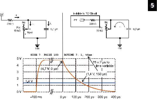
Figure 5-12 shows how the ReadPotWithRcTime.bs2’s HIGH, PAUSE and RCTIME commands interact with the circuit in Figure 5-11.
Figure 5-12: Voltage at P7 through HIGH, PAUSE, and RCTIME
On the left, the HIGH 7 command causes the BASIC Stamp to internally connect its I/O pin P7 to the 5 V supply (Vdd). Current from the supply flows through the potentiometer’s resistor and also charges the capacitor. The closer the capacitor gets to its final charge (almost 5 V), the less current flows into it. The PAUSE 100 command is primarily to make the Debug Terminal display update at about 10 times per second; PAUSE 1 is usually sufficient to charge the capacitor. On the right, the RCTIME 7, 1, time command changes the I/O pin direction from output to input and starts counting time in 2 μs increments. As an input the I/O pin no longer supplies the circuit with 5 V.

Page 154 · What’s a Microcontroller?
In fact, as an input, it’s pretty much invisible to the RC circuit. So, the capacitor starts losing its charge through the potentiometer. As the capacitor loses its charge, its voltage decays. The RCTIME command keeps counting time until P7 senses a low signal, meaning the voltage across the capacitor has decayed to 1.4 V, at which point it stores its measurement in the time variable.
Figure 5-12 also shows a graph of the voltage across the capacitor during the HIGH, PAUSE, and RCTIME commands. In response to the HIGH 7 command, which connects the circuit to 5 V, the capacitor quickly charges. Then, it remains level at its final voltage during most of the PAUSE 100 command. When the program gets to the RCTIME 7, 1, time command, it changes the I/O pin direction to input, so the capacitor starts to discharge through the potentiometer. As the capacitor discharges, the voltage at P7 decays. When the voltage decays to 1.4 V (at the 150 μs mark in this example), the RCTIME command stops counting time and stores the measurement result in the time variable. Since the RCTIME command counts time in 2 μs units, the result for 150 μs that gets stored in the time variable is 75.
I/O Pin Logic Threshold: 1.4 V is a BASIC Stamp 2 I/O pin’s logic threshold. When the I/O pin is set to input, it stores a 1 in its input register if the voltage applied is above 1.4 V or a 0 if the input voltage is 1.4 V or below. The first pushbutton example back in Chapter 3, Activity #2 applied either 5 V or 0 V to P3. Since 5 V is above 1.4 V, IN3 stored a 1, and since 0 V is below 1.4 V, IN3 stored a 0.
RCTIME State Argument: In ReadPotWithRcTime.bs2, the voltage across the capacitor decays from almost 5 V, and when it gets to 1.4 V, the value in the IN7 register changes from 1 to 0. At that point, the RCTIME command stores its measurement in its Duration, which is the time variable in the example program. The RCTIME command’s State argument is 1 in RCTIME 7, 1, time, which tells the RCTIME command that the IN7 register will store a 1 when the measurement starts. The RCTIME command measures how long it takes for the IN7 register to change to the opposite state, which happens when the voltage decays below the I/O pin’s 1.4 V logic threshold.
For more information: Look up the RCTIME command in either the BASIC Stamp Manual or the BASIC Stamp Editor’s Help.
Figure 5-13 shows how the decay time changes with the potentiometer’s resistance for the circuit in Figure 5-11. Each position of the potentiometer’s knob sets it at a certain resistance. Turn it further one direction, and the resistance increases, and in the other direction, the resistance decreases. When the resistance is larger, the decay takes a longer time, and the RCTIME command stores a larger value in the time variable. When the resistance is smaller, the decay takes a shorter time, and the RCTIME command stores a

Measuring Rotation · Page 155
smaller value in the time variable. The DEBUG command in ReadPotWithRcTime.bs2 displays this time measurement in the Debug Terminal, and since the decay time changes with the potentiometer’s resistance, which in turn changes with the potentiometer knob’s position, the number in the Debug Terminal indicates the knob’s position.
Figure 5-13
How Potentiometer Resistance
Affects Decay Time
Why does the capacitor charge to a lower voltage when the potentiometer has less resistance?
Take a look at the schematic in the upper-left corner of Figure 5-12 on page 153. Without the 220 Ω resistor, the I/O pin would be able to charge the capacitor to 5 V, but the 220 Ω resistor is necessary to prevent possible I/O pin damage from a current inrush when it starts charging the capacitor. It also prevents the potentiometer from drawing too much current if it is turned to 0 Ω while the I/O pin sends its 5 V high signal.
With 5 V applied across the 220 Ω resistor in series with the potentiometer, the voltage between them has to be some fraction of 5 V. When two resistors conducting current are placed in series, which results in an intermediate voltage, the circuit is called a voltage divider. So the 220 Ω resistor and potentiometer form a voltage divider circuit, and for any given potentiometer resistance (Rpot), you can use this equation to calculate the voltage across the potentiometer (Vpot):
Vpot = 5 V × Rpot ÷ (Rpot + 220 Ω)
The value of Vpot sets the ceiling on the capacitor’s voltage. In other words, whatever the voltage across the potentiometer would be if the capacitor wasn’t connected, that’s the voltage the capacitor can charge to, and no higher. For most of the potentiometer knob’s range, the resistance values are in the kΩ, and when you calculate Vpot for kΩ Rpot values, the results are pretty close to 5 V. The 220 Ω resistor doesn’t prevent Vpot from charging above 1.4 V until the potentiometer’s value is down at 85.6 Ω, which is less than 1% of the potentiometer’s range of motion. This 1% would have resulted in the lowest measurements anyhow, so it’s difficult to tell that measurements of 1 in this range are anything out of the ordinary. Even with the additional 220 Ω resistors built into BASIC Stamp HomeWork board I/O pin connections, only the lowest 1.7% of the potentiometer’s range is affected, so it’s still virtually unnoticeable.
So the 220 Ω resistor protects the I/O pin, with minimal impact on the RC decay measurement’s ability to tell you where you positioned the potentiometer’s knob.

Page 156 · What’s a Microcontroller?
ACTIVITY #4: CONTROLLING A SERVO WITH A POTENTIOMETER
Thumb joysticks like the one in Figure 5-14 are commonly found in video game controllers. Each joystick typically has two potentiometers that allow the electronics inside the game controller to report the joystick’s position to the video game console. One potentiometer rotates with the joystick’s horizontal motion (left/right), and the other rotates with the joystick’s vertical motion (forward/backward).
Horizontal
potentiometer Figure 5-14
Potentiometers Inside the Parallax Thumb Joystick Module
Vertical potentiometer
Another thumb joystick application that uses potentiometers is the RC radio controller and model airplane in Figure 4-1 on page 94. The controller has two joysticks, and each has two potentiometers. Each potentiometer’s position is responsible for controlling a different servo on the RC plane.
In this activity, you will use a potentiometer similar to the ones found in thumb joysticks to control a servo’s position. As you turn the potentiometer’s knob, the servo’s horn will mirror this motion. This activity utilizes two circuits, the potentiometer circuit from Activity #3 in this chapter, and the servo circuit from Chapter 4, Activity #1. The PBASIC program featured in this chapter repeatedly measures the potentiometer’s position with an RCTIME command, and then uses the measurement and some math to control the servo’s position with a PULSOUT command.

Measuring Rotation · Page 157
The BASIC Stamp can measure the joystick’s position. Since there are two potentiometers in each thumb joystick, each of them can replace the stand alone potentiometer in the circuits in Figure 5-11 on page 151. One RCTIME command can then measure the vertical potentiometer’s position, and another can measure the horizontal potentiometer.
Potentiometer Controlled Servo Parts
(1) Potentiometer – 10 kΩ
(1)Resistor – 220 Ω (red-red-brown)
(1)Resistor – 470 Ω (yellow-violet-brown)
(1)Capacitor – 0.1 µF
(1)Parallax Standard Servo
(1)LED – any color
(2)Jumper wires
HomeWork Board users will also need:
(1) 3-pin male-male header
(4) Jumper wires
Building the Dial and Servo Circuits
This activity will use two circuits that you have already built individually: the potentiometer circuit from the activity you just finished and the servo circuit from the previous chapter.
9Leave your potentiometer RC-time circuit from Activity #3 on your prototyping area. If you need to rebuild it, use Figure 5-11 on page 151. Make sure to use the 0.1 µF capacitor, not the 0.01 µF capacitor.
9Add your servo circuit from Chapter 4, Activity #1 to the project. Remember that your servo circuit will be different depending on your carrier board. Below are the pages for the sections that you will need to jump to:
o Page 96: Board of Education Servo Circuit
o Page 99: BASIC Stamp HomeWork Board Servo Circuit

Page 158 · What’s a Microcontroller?
Programming Potentiometer Control of the Servo
You will need the smallest and largest value of the time variable that you recorded from your RC-time circuit while using a 0.1 µF capacitor.
9If you have not already completed the Your Turn section of the previous activity, go back and complete it now.
For this next example, here are the time values that were measured by a Parallax technician; your values will probably be slightly different:
• All the way clockwise: |
1 |
•All the way counterclockwise: 691
So how can these input values be adjusted so that they map to the 500–1000 range for controlling the servo with the PULSOUT command? The answer is by using multiplication and addition. First, multiply the input values by something to make the difference between the clockwise (minimum) and counterclockwise (maximum) values 500 instead of almost 700. Then, add a constant value to the result so that its range is from 500 to 1000 instead of 1 to 500. In electronics, these operations are called scaling and offset.
Here’s how the math works for the multiplication (scaling):
time(maximum) = 691× 500691 = 691×0.724 = 500 time(minimum) =1× 500691 = 0.724
After the values are scaled, here is the addition (offset) step.
time(maximum) = 500 +500 = 1000 time(minimum) = 0.724 +500 = 500
The */ operator that was introduced on page 85 is built into PBASIC for scaling by fractional values, like 0.724. Here again are the steps for using */ applied to 0.724:
1.Place the value or variable you want to multiply by a fractional value before the */ operator.

Measuring Rotation · Page 159
time = time */
2.Take the fractional value that you want to use and multiply it by 256. new fractional value = 0.724× 256 =185.344
3.Round off to get rid of anything to the right of the decimal point. new fractional value = 185
4.Place that value after the */ operator.
time = time */ 185
That takes care of the scaling, now all we need to do is add the offset of 500. This can be done with a second command that adds 500 to time:
time = time */ 185 time = time + 500
Now, time is ready to be recycled into the PULSOUT command’s Duration argument.
time |
= time |
*/ 185 |
' Scale by 0.724. |
time |
= time |
+ 500 |
' Offset by 500. |
PULSOUT 14, |
time |
' Send pulse to servo. |
|
Example Program: ControlServoWithPot.bs2
9Enter and run this program, then twist the potentiometer’s knob and make sure that the servo’s movements echo the potentiometer’s movements.
'What's a Microcontroller - ControlServoWithPot.bs2
'Read potentiometer in RC-time circuit using RCTIME command.
'Scale time by 0.724 and offset by 500 for the servo.
'{$STAMP BS2}
'{$PBASIC 2.5}
PAUSE 1000
DEBUG "Program Running!"
time VAR Word

Page 160 · What’s a Microcontroller?
DO |
|
|
|
|
HIGH 7 |
|
|
|
|
PAUSE 10 |
|
|
|
|
RCTIME |
7, 1, time |
' Scale by 0.724 |
(X 256 for */). |
|
time = |
time |
*/ 185 |
||
time = |
time |
+ 500 |
' Offset by 500. |
|
PULSOUT 14, |
time |
' Send pulse to servo. |
||
LOOP
Your Turn – Scaling the Servo’s Relationship to the Dial
Your potentiometer and capacitor will probably give you time values that are somewhat different from the ones discussed in this activity. These are the values you gathered in the Your Turn section of the previous activity.
9Repeat the math discussed in the Programming Potentiometer Control of the Servo section on page 158 using your maximum and minimum values.
9Substitute your scale and offset values in ControlServoWithPot.bs2.
9Comment out DEBUG "Program Running!" with an apostrophe at the beginning of that line.
9Add this line of code between the PULSOUT and LOOP commands so that you can view your results:
DEBUG HOME, DEC5 time |
' Display adjusted time value. |
9Run the modified program and check your work. Because the values were rounded off, the limits may not be exactly 500 and 1000, but they should be pretty close.
Declaring Constants and Pin Directives
In larger programs, you may end up using the value of the scale factor (which was 185) and the offset (which was 500) many times in the program. Numbers like 185 and 500 in your program are called constants because unlike variables, their values cannot be changed while the program is running. In other words, the value remains “constant.” You can create names for these constants with CON directives:
ScaleFactor |
CON |
185 |
Offset |
CON |
500 |
delay |
CON |
10 |