

Whats A Microcontroller v3
.0.pdf
|
Measuring Light · Page 221 |
DO |
' Main routine. |
GOSUB Get_Rc_Time
GOSUB Delay
GOSUB Update_Display
LOOP
|
' |
Subroutines |
Get_Rc_Time: |
' |
RC-time subroutine |
HIGH 2 |
|
PAUSE 3 |
|
RCTIME |
2, 1, time |
RETURN |
|
Delay: |
' Delay subroutine. |
PAUSE time / 3 |
|
RETURN |
|
Update_Display: |
' Display updating subroutine. |
IF index = 6 THEN index = 0 |
|
' |
BAFG.CDE |
LOOKUP index, [ %01000000, |
|
%10000000,
%00000100,
%00000010,
%00000001, %00100000 ], OUTH
index = index + 1 RETURN
How LightMeter.bs2 Works
The first two lines of the program declare variables. It doesn’t matter whether these variables are used in subroutines or the main routine, it’s always best to declare variables (and constants) at the beginning of your program.
Since this is such a common practice, this section of code has a name, “Variable declarations.” This name is shown in the comment to the right of the first variable declaration.
index VAR |
Nib |
' Variable declarations. |
time VAR |
Word |
|
Page 222 · What’s a Microcontroller?
Many programs also have things that need to get done once at the beginning of the program. Setting all the 7-segment I/O pins low and then making them outputs is an example. This section of a PBASIC program also has a name, “Initialization.”
OUTH |
= |
%00000000 |
' Initialize 7-segment display. |
DIRH |
= |
%11111111 |
|
The next segment of code is called the main routine. The main routine calls the Get_Rc_Time subroutine first. Then, it calls the Delay subroutine, and after that, it calls the Update_Display subroutine. Keep in mind that the program goes through the three subroutines as fast as it can, over and over again.
DO |
' Main routine. |
GOSUB Get_Rc_Time |
|
GOSUB Delay |
|
GOSUB Update_Display |
|
LOOP |
|
All subroutines are usually placed after the main routine. The first subroutine’s name is Get_Rc_Time:, and it takes the RC-time measurement on the phototransistor circuit. This subroutine has a PAUSE command that charges up the capacitor. The Duration of this command is small because it only needs to pause long enough to make sure the capacitor is charged. Note that the RCTIME command sets the value of the time variable. This variable will be used by the second subroutine.
Get_Rc_Time: |
' Subroutines |
' RC-time subroutine |
|
HIGH 2 |
|
PAUSE 3 |
|
RCTIME 2, 1, time |
|
RETURN |
|
The second subroutine’s name is Delay, and all it contains is PAUSE time / 3. The PAUSE command allows the measured decay time (how bright the light is) to control the delay between turning on each light segment in the 7-segment LED’s revolving circular display. The value to the right of the divide / operator can be made larger for faster rotation in lower light conditions or smaller to slow the display for brighter light conditions. You could also use * to multiply the time variable by a value instead of dividing to make the display go a lot slower, and for more precise control over the rate, don’t forget about the */ operator. More on this operator in the Your Turn section.

Measuring Light · Page 223
Delay:
PAUSE time / 3
RETURN
The third subroutine is named Update_Display. The LOOKUP command in this subroutine contains a table with six bit patterns that are used to create the circular pattern around the outside of the 7-segment LED display. By adding 1 to the index variable each time the subroutine is called, it causes the next bit pattern in the sequence to get placed in OUTH. There are only six entries in the LOOKUP table for index values from 0 through 5. What happens when the value of index gets to 6? The LOOKUP command doesn’t automatically know to go back to the first entry, but you can use an IF...THEN statement to fix that problem. The command IF index = 6 THEN index = 0 resets the value of index to 0 each time it gets to 6. It also causes the sequence of bit patterns placed in OUTH to repeat itself over and over again. This, in turn, causes the 7-segment LED display to repeat its circular pattern over and over again.
Update_Display:
IF index = 6 THEN index = 0 ' BAFG.CDE LOOKUP index, [ %01000000,
%10000000,
%00000100,
%00000010,
%00000001, %00100000 ], OUTH
index = index + 1 RETURN
Your Turn – Adjusting the Meter’s Hardware and Software
There are two ways to change the sensitivity of the meter. First the “software,” which is the PBASIC program, can be changed to adjust the speed. As mentioned earlier, dividing the time variable in the Delay subroutine’s PAUSE time / 3 command by numbers larger than 3 will speed up the display, and smaller numbers will slow it down. To really slow it down, time can also be multiplied by values with the multiply * operator, and for fine tuning, there’s the */ operator.
When you connect capacitors in parallel, their values add up. So, if you plug in a second 0.01 μF capacitor right next to the first one as shown in Figure 7-14 and Figure 7-15, the

Page 224 · What’s a Microcontroller?
capacitance will be 0.02 μF. With twice the capacitance, the decay measurement for the same light level will take twice as long.
9Connect the second 0.01 μF capacitor right next to the first one in the light sensor portion of the light meters circuit in Figure 7-14 and Figure 7-15.
9Run LightMeter.bs2 and observe the result.
Since the time measurements will be twice as large, the 7-segment LED’s circular pattern should rotate half as fast.
Figure 7-14
Two 0.01 μF Capacitors
in Parallel = 0.02 μF
Figure 7-15
Light Meter Circuits with Two 0.01 μF Capacitors in Parallel
Instead of half the speed of a 0.01 μF capacitor, how about one tenth the speed? You can do this by replacing the two 0.01 μF capacitors with a 0.1 μF capacitor. It will work okay in brightly lit rooms, but will likely be a little slow for normal lighting. Remember that when you use a capacitor that is ten times as large, the RC-time measurement will take ten times as long.
Measuring Light · Page 225
9Replace the 0.01 µF capacitors with a 0.1 µF capacitor.
9Run the program and see if the predicted effect occurred.
9Before continuing, restore the circuit to one 0.01 µF capacitor in parallel with the phototransistor as shown in Figure 7-9 and Figure 7-10, starting on page 215.
9Test your restored circuit to verify that it works before continuing.
Which is better, adjusting the software or the hardware? You should always try to use the best of both worlds. Pick a capacitor that gives you the most accurate measurements over the widest range of light levels. Once your hardware is the best it can be, use the software to automatically adjust the light meter so that it works well for the user under the widest range of conditions. This takes a considerable amount of testing and refinement, but that’s all part of the product design process.
ACTIVITY #5: ON/OFF PHOTOTRANSISTOR OUTPUT
Before microcontrollers were common in products, photoresistors were used in circuits that varied in their voltage output. When the voltage passed below a threshold value indicating nighttime, other circuits in the device turned the lights on. When the voltage passed above the threshold, indicating daytime, the other circuits in the device turned the lights off. This binary light switch behavior can be emulated with the same BASIC Stamp and the RC decay circuit by simply modifying the PBASIC program. Alternatively, the circuit can be modified so that it sends a 1 or 0 to an I/O pin depending on the amount of voltage supplied to the pin, similar to the way a pushbutton does. In this activity, you will try both these approaches.
Adjusting the Program for On/Off States
PhototransistorAnalogToBinary.bs2 takes the range of phototransistor measurements and compares it to the half way point between the largest and smallest measurements. If the measurement is above the half way point, it displays “Turn light on”; otherwise, it displays “Turn light off.” The program uses constant directives to define the largest and smallest measurements the program should expect from the phototransistor circuit.
valMax |
CON |
4000 |
valMin |
CON |
100 |
Page 226 · What’s a Microcontroller?
The program also uses MIN and MAX operators to ensure that values stay within these limits before using them to make any decisions. If time is greater than valMax (4000 in the example program), the statement sets time to valMax = 4000. Likewise if time is less than valMin (100 in the example program), the statement sets time to valMin =
100.
time = time MAX valMax MIN valMin
An IF...THEN...ELSE statement converts the range of digitized analog values into a binary output that takes the form of light-on or light-off messages.
IF time > (valMax - valMin) / 2 THEN
DEBUG CR, "Turn light on "
ELSE
DEBUG CR, "Turn light off"
ENDIF
Before this program will work properly, you have to calibrate your lighting conditions as follows:
9Check your phototransistor circuit to make sure it has just one 0.01 μF capacitor (labeled 103).
9Enter PhototransistorAnalogToBinary.bs2 into the BASIC Stamp Editor. Make sure to add an extra space after the "n" in the "Turn light on " message. Otherwise, you’ll get a phantom "f" from the "Turn light off" message, which has one more character in it.
9Load the program into the BASIC Stamp.
9Watch the Debug Terminal as you apply the darkest and brightest lighting conditions that you want to test, and make notes of the resulting maximum and minimum time values.
9Enter those values into the program’s valMax and valMin CON directives.
Now, your program is ready to run and test.
9Load the modified program into the BASIC Stamp.
9Test to verify that dim lighting conditions result in the “Turn Light on” message and bright lighting conditions result in the “Turn light off” message.

Measuring Light · Page 227
'What's a Microcontroller - PhototransistorAnalogToBinary.bs2
'Change digitized analog phototransistor measurement to a binary result.
'{$STAMP BS2}
'{$PBASIC 2.5}
valMax |
CON |
4000 |
valMin |
CON |
100 |
time |
VAR |
Word |
PAUSE 1000 |
|
|
DO |
|
|
HIGH 2
PAUSE 100
RCTIME 2, 1, time
time = time MAX valMax MIN valMin
DEBUG HOME, "time = ", DEC5 time
IF time > (valMax - valMin) / 2 THEN
DEBUG CR, "Turn light on "
ELSE
DEBUG CR, "Turn light off"
ENDIF
LOOP
Your Turn – Different Thresholds for Light and Dark
If you try to incorporate PhototransistorAnalogToBinary.bs2 into an automatic lighting system, it has a potential defect. Let’s say it’s dark enough outside to cause the time measurement to pass above (valMax – valMin) / 2, so the light turns on. But if the sensor detects that light, it would cause the measurement to pass back below (valMax – valMin) / 2, so the light would turn off again. This lights-on/lights-off cycle could repeat rapidly all night!
Page 228 · What’s a Microcontroller?
Figure 7-16 shows how this could work in a graph. As the light level drops, the value of the time variable increases, and when it crosses the threshold, the automatic lights turn on. Then, since the phototransistor senses the light that just turned on, the time variable’s measurement drops back below the threshold, so the lights turn off. Then, the time variable’s value increases again, and it passes above the threshold, so the lights turn on, and the time variable drops below the threshold again, and so on…
valMax
"Turn light on "
Figure 7-16
(valMax - valMin) / 2 |
|
Oscillations |
|
||
|
|
|
|
|
Above/Below a |
|
"Turn light off" |
Threshold |
valMin |
|
|
|
|
|
|
|
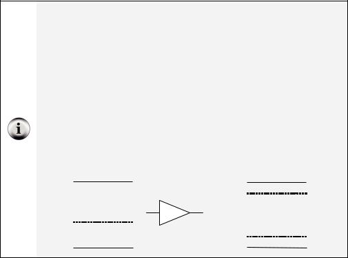
One remedy for this problem is to add a second threshold, as illustrated in Figure 7-17. The “Turn light on” threshold only turns the light on after it’s gotten pretty dark, and the “Turn light off” threshold only turns the light back off after it’s gotten pretty bright. With this system, the light comes on after time passed into the “Turn light on” range. The light turning on made it brighter, so time dropped slightly, but since it didn’t fall clear down past the “Turn light off” threshold, nothing changed, and the light stays on as it should. The term hysteresis is used to describe this type of system, which has two different input thresholds that affect its output along with a no-transition zone between them.
valMax |
|
|
|
|
|
|
|
|
|
|
|
|
|
|
|
|
|
|
|
|
|
|
|
|
|
|
|
|
|
|
|
|
|
|
|
|
|
|
|
|
|
|
|
|
|
|
|
|
|
|
|
|
|
|
|
|
|
|
|
|
|
|
|
|
|
|
|
|
|
|
|
|
|
|
|
|
|
|
|
|
|
|
|
|
|
|
|
|
|
|
|
|
|
|
|
|
"Turn light on " |
|
|||||||||||||||||||||||||||||||||||||||||||
(valMax - valMin) / 4 * 3 |
|
|
|
|
|
|
|
|
|
|
|
|
|
|
|
|
|
|
|
|
|
|
|
|
|
|
|
|
||||||||||||||||||||||||||||||||||||||||||
|
|
|
|
|
|
|
|
|
|
|
|
|
|
|
|
|
|
|
|
|
|
|
|
|
|
|
|
|
|
|
|
|
|
|
|
|
|
|
|
|
|
|
|
|
|
|
|
|
|
|
|
|
|
|
|
|
|
|
|
|
|
|
|
|
|
|
|
Figure 7-17 |
||
|
|
|
|
|
|
|
|
|
|
|
|
|
|
|
|
|
|
|
|
|
|
|
|
|
|
|
|
No transition |
||||||||||||||||||||||||||||||||||||||||||
|
|
|
|
|
|
|
|
|
|
|
|
|
|
|
|
|
|
|
|
|
|
|
|
|
|
|
|
|
|
|||||||||||||||||||||||||||||||||||||||||
|
|
|
|
|
|
|
|
|
|
|
|
|
|
|
|
|
|
|
|
|
|
|
|
|
|
|
|
|
|
Using Different High |
||||||||||||||||||||||||||||||||||||||||
|
|
|
|
|
|
|
|
|
|
|
|
|
|
|
|
|
|
|
|
|
|
|
|
|
|
|
|
|
|
|
|
|
|
|
|
|
|
|
|
|
|
|
|
|
|
|
|
|
|
|
|
|
|
|
|
|
|
|
|
|
|
|
|
|
|
|
|
|
|
and Low Thresholds |
(valMax - valMin) / 4 |
|
|
|
|
|
|
|
|
|
|
|
|
|
|
|
|
|
|
|
|
|
|
|
|
|
|
|
|
|
|
|
|
|
|
|
|
|
|
|
|
|
to Prevent |
||||||||||||||||||||||||||||
|
|
|
|
|
|
|
|
|
|
|
|
|
|
|
|
|
|
|
|
|
|
|
|
|
"Turn light off" |
|||||||||||||||||||||||||||||||||||||||||||||
valMin |
|
|
|
|
|
|
|
|
|
|
|
|
|
|
|
|
|
|
|
|
|
|
|
|
Oscillations |
|||||||||||||||||||||||||||||||||||||||||||||
|
|
|||||||||||||||||||||||||||||||||||||||||||||||||||||||||||||||||||||
|
|
|||||||||||||||||||||||||||||||||||||||||||||||||||||||||||||||||||||

Measuring Light · Page 229
You can implement this two-threshold system in your PBASIC code by modifying PhotransistorAnalogToBinary.bs2’s IF...THEN...ELSEIF statement. Here is an example:
IF time > (valMax - valMin) / 4 * 3 THEN
DEBUG CR, "Turn light on "
ELSEIF time < (valMax - valMin ) / 4 THEN
DEBUG CR, "Turn light off"
ENDIF
The first IF...THEN code block displays "Turn lights on " when the time variable stores a value that’s more than ¾ of the way to the highest time (lowest light) value. The ELISIF code block only displays "Turn lights off" when the time variable stores a value that’s less than ¼ of the way above the smallest time (brightest) value.
9Save PhototransistorAnalogToBinary.bs2 as PhotransistorHysteresis.bs2.
9Before modifying PhotransistorHysteresis.bs2, test it to make sure the existing threshold works. If the lighting has changed, repeat valMin and valMax calibration steps (before the PhototransistorAnalogToBinary.bs2 example code).
9Replace PhotransistorHysteresis.bs2’s IF...ELSE...ENDIF statement with the
IF...ELSEIF...ENDIF just discussed.
9Load the PhotransistorHysteresis.bs2 into the BASIC Stamp.
9Test and verify that the “Turn light on” threshold is darker, and the “Turn light off” threshold is lighter.
If you add an LED circuit and modify the code so that it turns the LED on and off, some interesting things might happen. Especially if you put the LED right next to the phototransistor, you might still see that on/off behavior when it gets dark, even with the hysteresis programmed. How far away from the phototransistor does the LED have to be to get the two thresholds to prevent the on/off behavior? Assuming that valMin and valMax are the same in both programs, how much farther away does the LED have to be for the unmodified PhototransistorAnalogToBinary.bs2 to work properly?
Page 230 · What’s a Microcontroller?
TTL Vs. Schmitt Trigger
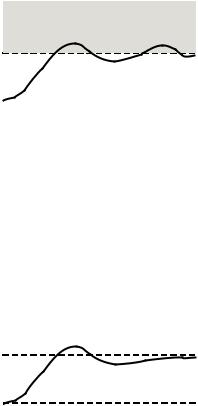
Your BASIC Stamp I/O pin sends and receives signals using transistor-transistor logic (TTL). As an output, the I/O pin sends a 5 V high signal or a 0 V low signal. The left side of Figure 7-18 shows how the I/O pin behaves as an input. The I/O pin’s IN register (IN0, IN1, IN2, etc.) stores a 1 if the voltage applied is above 1.4 V, or a 0 if it’s below 1.4 V. These are shown as Logic 1 and Logic 0 in the figure.
A Schmitt trigger is a circuit represented by the symbol in the center of Figure 7-18. The right side of Figure 7-18 shows how an I/O pin set to input would behave if it had a Schmitt trigger circuit built-in. Like the PBASIC code with two thresholds, the Schmitt trigger has hysteresis. The input value stored by the I/O pin’s INx register doesn’t change from 0 to 1 until the input voltage goes above 4.25 V. Likewise, it doesn’t change from 1 to 0 until the input voltage passes below 0.75 V. The BASIC Stamp 2px has a PBASIC command that allows you to configure its input pins to Schmitt trigger.
Figure 7-18 TTL Vs. Schmitt Trigger Thresholds and Symbol
|
TTL |
Schmitt Trigger |
|
Schmitt Trigger |
||||
|
Threshold |
|
Symbol |
|
Threshold |
|||
5 V |
|
|
|
|
|
|
5 V |
|
|
|
|
|
|
|
Logic 1 |
||
|
|
|
|
|
|
|
≈4.25 V |
|
|
Logic 1 |
|
|
|
|
|
|
|
|
|
|
|
|
|
|
|
|
≈1.4 V |
|
|
|
|
|
|
|
No Change |
|
|
|
|
|
|
|
||
|
|
|
|
|
|
|
||
|
|
|
|
|
|
|
|
|
Logic 0 |
|
|
|
|
|
≈0.75 V |
|
|
|
|
|
|
|
|
|
||
|
|
|
|
|
|
|
Logic 0 |
|
0 V |
|
|
|
|
|
|
0 V |
|
|
|
|
|
|
|
|
||
Adjusting the Circuit for On/Off States
As mentioned in Chapter 5, Activity #2, the voltage threshold for a BASIC Stamp I/O pin is 1.4 V. When an I/O pin is set to input, voltages above 1.4 V applied to the I/O pin result in a binary 1 and voltages below 1.4 V result in a binary 0. The Vo node in the circuit shown in Figure 7-19 varies in voltage with light. This circuit can be connected to a BASIC Stamp I/O pin, and with low light, the voltage will pass below the BASIC Stamp’s 1.4 V threshold, and the I/O pin’s input register will store a 0. In bright light conditions, Vo rises above 1.4 V, and the I/O pin’s input register will store a 1.