

Whats A Microcontroller v3
.0.pdfDigital Display · Page 181
The first command:
OUTH = %00000000
...gets all the I/O pins (P8 through P15) ready to send the low signals. If they all send low signals, it will turn all the LEDs in the 7-segment LED display off. If you wanted all the I/O pins to send a high signal, you could use OUTH = %11111111 instead.
What does % do? The % binary formatter is used to tell the BASIC Stamp Editor that the number is a binary number. For example, the binary number %00001100 is the same as the decimal number 12. As you will see in this activity, binary numbers can make many programming tasks much easier.
The low signals will not actually be sent by the I/O pins until you use the DIRH variable to change all the I/O pins from input to output. The command:
DIRH = %11111111
...sets I/O pins P8 through P15 to output. As soon as this command is executed, P8 through P15 all start sending low signals. This is because the command OUTH = %00000000 was executed just before this DIRH command. As soon as the DIRH command set all the I/O pins to output, they started sending their low signals. You can also use DIRH = %00000000 to change all the I/O pins back to inputs.
Before I/O pins become outputs: Up until the I/O pins are changed from input to output, they just listen for signals and update the INH variable. This is the variable that contains IN8, IN9, up through IN15. These variables can be used the same way that IN3 and IN4 were used for reading pushbuttons in Chapter 3 Digital Input – Pushbuttons.
All BASIC Stamp I/O pins start out as inputs. This is called a default. You have to tell a BASIC Stamp I/O pin to become an output before it starts sending a high or low signal. Both the HIGH and LOW commands automatically change a BASIC Stamp I/O pin’s direction to output. Placing a 1 in the DIRH variable also makes one of the I/O pins an output.
Always set values in a given OUT register before making them outputs with values in the corresponding DIR register. This prevents briefly sending unintended signals. For example, if DIR5 = 1 is followed by OUT5 = 1 at the beginning of a program, it will briefly send an unintended low signal before switching to high because OUT5 stores 0 when the program starts. (All PBASIC variables/registers initialize to 0.) If OUT5 = 1 is instead followed by DIR5 = 1, the I/O pin will send a high signal as soon as it becomes an output.
Since the values stored by all variables default to 0 when the program starts, the command OUTH = %00000000 is actually redundant.
Page 182 · What’s a Microcontroller?
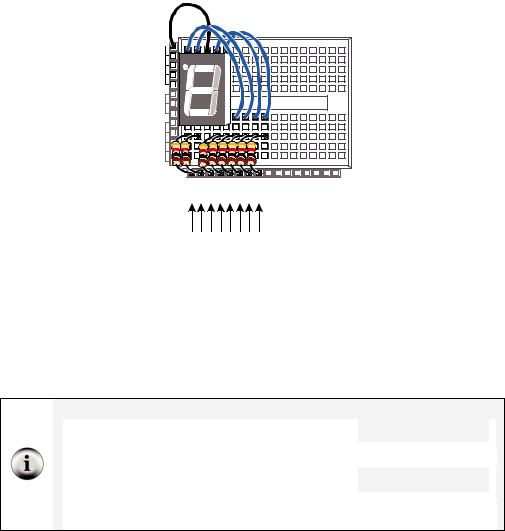
Figure 6-14 shows how to use the OUTH variable to selectively send high and low signals to P8 through P15. A binary-1 is used to send a high signal, and a binary-0 is used to send a low signal. This example displays the number three on the 7-segment LED display:
' BAFG.CDE
OUTH = %11010110
Vss |
|
Vin |
Figure 6-14 |
|
|
Vdd |
Using OUTH to Control |
the High/Low Signals of |
|
X3 |
P8 – P15 |
P15 P14 P13 P12 P11 P10 P9 P8 P7 P6 P5 P4 P3 P2 P1 P0 X2 |
‘ BAFG.CDE OUTH = %11010110
The display is turned so that the three on the display is upside-down because it more clearly shows how the values in OUTH line up with the I/O pins. The command OUTH = %11010110 uses binary zeros to set I/O pins P8, P11, and P13 low, and it uses binary ones to set P9, P10, P12, P14 and P15 high. The line just before the command is a comment that shows the segment labels line up with the binary value that turns that segment on/off.
Inside the HIGH and LOW commands:
HIGH 15 |
...is really the same as: |
|
OUT15 = 1 |
|
Likewise, the command : |
|
|
DIR15 = 1 |
|
|
|
|
||
|
|
|
||
|
|
|
|
|
LOW 15 |
...is the same as: |
|
OUT15 = 0 |
|
|
|
|
DIR15 = 1 |
|
If you want to change P15 back to an input, use DIR15 |
= |
0. You can then use IN15 to |
||
detect (instead of send) high/low signals. |
|
|
||
|
|
|
|
|

Digital Display · Page 183
Your Turn – Displaying A through F
9Figure out what bit patterns (combinations of zeros and ones) you will need to display the letters A, b, C, d, E, and F.
9Modify DisplayDigits.bs2 so that it displays A, b, C, d, E, F.
Decimal vs. Hexadecimal The basic digits in the decimal (base-10) number system are:
0, 1, 2, 3, 4, 5, 6, 7, 8, 9
In the hexadecimal (base-16) number system the basic digits are:
0, 1, 2, 3, 4, 5, 6, 7, 8, 9, A, b, C, d, E, F.
Base-16 is used extensively in both computer and microcontroller programming. Once you figure out how to display the characters A through F, you can further modify your program to count in hexadecimal from 0 to F.
Keeping Lists of On/Off Patterns
The LOOKUP command makes writing code for 7-segment LED display patterns much easier. The LOOKUP command lets you “look up” elements in a list. Here is a code example that uses the LOOKUP command:
LOOKUP index, [7, 85, 19, 167, 28], value
There are two variables used in this command, index and value. If the index is 0, value stores 7. If index is 1, value stores 85. In the next example program, index is set to 2, so the LOOKUP command places 19 into value, and that’s what the Debug Terminal displays.
Example Program: SimpleLookup.bs2
9Enter and run SimpleLookup.bs2.
9Run the program as-is, with the index variable set equal to 2.
9Try setting the index variable equal to numbers between 0 and 4.
9Re-run the program after each change to the index variable and note which value from the list gets placed in the value variable.
9Optional: Modify the program by placing the LOOKUP command in a FOR...NEXT loop that counts from 0 to 4.

Page 184 · What’s a Microcontroller?
'What's a Microcontroller - SimpleLookup.bs2
'Debug a value using an index and a lookup table.
'{$STAMP BS2}
'{$PBASIC 2.5}
value |
VAR |
Byte |
index |
VAR |
Nib |
index = 2 |
|
|
PAUSE 1000 |
|
|
DEBUG ? index |
|
|
LOOKUP index, [7, 85, 19, 167, 28], value
DEBUG ? value, CR
DEBUG "Change the index variable to a ", CR, "different number(between 0 and 4).", CR, CR,
"Run the modified program and ", CR, "check to see what number the", CR, "LOOKUP command places in the", CR, "value variable."
END
Example Program: DisplayDigitsWithLookup.bs2
This example program shows how the LOOKUP command can come in really handy for storing the bit patterns used in the OUTH variable. Again, the index variable is used to choose which binary value is placed into the OUTH variable. This example program counts from 0 to 9 again. The difference between this program and DisplayDigits.bs2 is that this program is much more versatile. It is much quicker and easier to adjust for different number sequences using lookup tables.
9Enter and run DisplayDigitsWithLookup.bs2.
9Verify that it does the same thing as the previous program (with much less work).
9Take a look at the Debug Terminal while the program runs. It shows how the value of index is used by the LOOKUP command to load the correct binary value from the list into OUTH.

Digital Display · Page 185
'What's a Microcontroller - DisplayDigitsWithLookup.bs2
'Use a lookup table to store and display digits with a 7-segment LED display.
'{$STAMP BS2} '{$PBASIC 2.5}
index |
VAR |
Nib |
OUTH = %00000000 |
|
|
DIRH = %11111111 |
|
|
PAUSE 1000 |
|
|
DEBUG "index |
OUTH |
", CR, |
"----- |
--------", CR |
|
FOR index = 0 TO 9
LOOKUP index, [ %11100111, %10000100, %11010011, %11010110, %10110100, %01110110,
%01110111, %11000100, %11110111, %11110110 ], OUTH
DEBUG " ", DEC2 index, " ", BIN8 OUTH, CR
PAUSE 1000
NEXT
DIRH = %00000000
END
Your Turn – Displaying 0 through F Again
9Modify DisplayDigitsWithLookup.bs2 so that it counts from 0 through F in hexadecimal. Don’t forget to update the FOR...NEXT loop’s EndValue argument.
ACTIVITY #4: DISPLAYING THE POSITION OF A DIAL
In Chapter 5, Activity #4 you used the potentiometer to control the position of a servo. In this activity, you will display the position of the potentiometer using the 7-segment LED display.
Dial and Display Parts
(1) 7-segment LED display
(8) Resistors – 1 kΩ (brown-black-red)
(1) Potentiometer – 10 kΩ
(1) Resistor – 220 Ω (red-red-brown)
(1) Capacitor – 0.1 µF
(7) Jumper wires
Page 186 · What’s a Microcontroller?
Building the Dial and Display Circuits
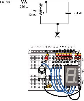
Figure 6-15 shows a schematic of the potentiometer circuit that should be added to the project. Figure 6-16 shows a wiring diagram of the circuit from Figure 6-15 combined with the circuit from Figure 6-11 on page 176.
9Add the potentiometer circuit to the 7-segment LED display circuit as shown in Figure 6-16.
Figure 6-15
Schematic of
Potentiometer Circuit
Added to the Project
Figure 6-16
Wiring Diagram for
Figure 6-15
Programming the Dial and Display
There is a useful command called LOOKDOWN, and yes, it is the reverse of the LOOKUP command. While the LOOKUP command gives you a number based on an index, the LOOKDOWN command gives you an index based on a number.
Digital Display · Page 187
Example Program: SimpleLookdown.bs2
This example program demonstrates how the LOOKDOWN command works.
9Enter and run SimpleLookdown.bs2.
9Run the program as-is, with the value variable set equal to 167, and use the Debug Terminal to observe the value of index.
9Try setting the value variable equal to each of the other numbers listed by the LOOKDOWN command: 7, 85, 19, 28.
9Re-run the program after each change to the value variable and note which value from the list gets placed in the index variable.
Trick question: What happens if your value is greater than 167? This little twist in the LOOKDOWN command can cause problems because the LOOKDOWN command doesn’t make any changes to the index.
'What's a Microcontroller - SimpleLookdown.bs2
'Debug an index using a value and a lookup table.
'{$STAMP BS2}
'{$PBASIC 2.5}
value |
VAR |
Byte |
index |
VAR |
Nib |
value = 167 |
|
|
PAUSE 1000 |
|
|
DEBUG ? value |
|
|
LOOKDOWN value, [7, 85, 19, 167, 28], index
DEBUG ? index, CR
DEBUG "Change the value variable to a ", CR, "different number in this list:", CR, "7, 85, 19, 167, or 28.", CR, CR,
"Run the modified program and ", CR, "check to see what number the ", CR, "LOOKDOWN command places in the ", CR, "index variable."
END
Page 188 · What’s a Microcontroller?
Unless you tell it to make a different kind of comparison, the LOOKDOWN command checks to see if a value is equal to an entry in the list. You can also check to see if a value is greater than, less than or equal to, etc. For example, to search for an entry that the value variable is less than or equal to, use the <= operator just before the first bracket that starts the list. In other words, the operator returns the index of the first value in the list that makes the statement in the instruction true.
9Modify SimpleLookdown.bs2 by substituting this value and LOOKDOWN statement in place of the existing ones:
value = 35
LOOKDOWN value, <= [ 7, 19, 28, 85, 167 ], index
9 Modify the DEBUG command so that it reads:
DEBUG "Change the value variable to a ", CR, "different number in this range:", CR, "0 to 170.", CR, CR,
"Run the modified program and ", CR, "check to see what number the ", CR, "LOOKDOWN command places in the ", CR, "index variable."
9Experiment with different values and see if the index variable displays what you would expect.
Example Program: DialDisplay.bs2
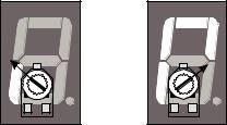
This example program mirrors the position of the potentiometer’s knob by lighting segments around the outside of the 7-segment LED display as shown in Figure 6-17.
Figure 6-17
Displaying the Potentiometer’s
Position with the 7-Segment LED
Display

Digital Display · Page 189
9Enter and run DialDisplay.bs2.
9Twist the potentiometer’s knob and make sure it works. Remember to press down to keep the pot seated in the breadboard.
9When you run the example program, it may not be as precise as shown in Figure 6-17. Adjust the values in the LOOKDOWN table so that that the digital display more accurately depicts the position of the potentiometer.
'What's a Microcontroller - DialDisplay.bs2
'Display POT position using 7-segment LED display.
'{$STAMP BS2} '{$PBASIC 2.5}
PAUSE 1000
DEBUG "Program Running!"
index |
VAR |
Nib |
time |
VAR |
Word |
OUTH = %00000000
DIRH = %11111111
DO
HIGH 5
PAUSE 100
RCTIME 5, 1, time
LOOKDOWN time, <= [40, 150, 275, 400, 550, 800], index
LOOKUP index, [ %11100101, %11100001, %01100001, %00100001, %00000001, %00000000 ], OUTH
LOOP
How DialDisplay.bs2 Works
This example program takes an RCTIME measurement of the potentiometer and stores it in a variable named time.
HIGH 5
PAUSE 100
RCTIME 5, 1, time

Page 190 · What’s a Microcontroller?
The time variable is then used in a LOOKDOWN table. The LOOKDOWN table decides which number in the list time is smaller than, and then loads the entry number (0 to 5 in this case) into the index variable.
LOOKDOWN time, <= [40, 150, 275, 400, 550, 800], index
Next, the index variable is used in a LOOKUP table to choose the binary value to load into the OUTH variable.
LOOKUP index, [ %11100101, %11100001, %01100001, %00100001, %00000001, %00000000 ], OUTH
Your Turn – Adding a Segment
DialDisplay.bs2 only makes five of the six segments turn on when you turn the dial. The sequence for turning the LEDs on in DialDisplay.bs2 is E, F, A, B, C, but not D.
9Save DialDisplay.bs2 under the name DialDisplayYourTurn.bs2.
9Modify DialDisplayYourTurn.bs2 so that it causes all six outer LEDs to turn on in sequence as the potentiometer is turned. The sequence should be: E, F, A, B, C, and D.
Tip: Leave your 7-segment LED circuit on your board. We’ll be using the 7-segment LED again along with other circuits in Chapter 7, Activity #4.