

Whats A Microcontroller v3
.0.pdf
|
Electronic Building Blocks · Page 301 |
ELSE |
|
DEBUG CR, "New and old settings", CR, |
|
"are the same, try ", CR, |
|
"again...", CR |
' Give reader time to view |
PAUSE DelayReader |
|
ENDIF |
' Message. |
RETURN |
|
Pulse_Clk_pin: |
|
'Deliver pulses from old to new values. Keep in mind that Set_Ud_Pin
'adjusted the value of oldTapSetting toward newTapSetting by one.
'This keeps the FOR...NEXT loop from executing one too many times.
FOR counter = oldTapSetting TO newTapSetting
PULSOUT ClkPin, 1
PAUSE DelayPulses
NEXT
oldTapSetting = newTapSetting |
' |
Keep track |
of new and old |
RETURN |
' |
tapSetting |
values. |
|
|
|
Page 302 · What’s a Microcontroller?
SUMMARY
This chapter introduced integrated circuits and how they can be used with the BASIC Stamp. A transistor was used as a current valve, and a digital potentiometer was used to control the amount of current passing through the transistor. Examining the digital potentiometer introduced the reference notch and pin map as important elements of electronic chips. The function of each of the digital potentiometer pins was discussed, as well as the device’s internal structure. The PBASIC command TOGGLE was introduced as a means to save program memory.
Questions
1.What are the names of the terminals on the transistor you used in this chapter?
2.Which terminal controls the current passing through the transistor?
3.What can you do to increase or decrease the current passing through the transistor?
Exercise
1.Write a program that adjusts the tap in the digital pot to position 0 regardless of its current setting.
Project - Advanced Challenge
1.Add a phototransistor to your project and cause the brightness of the LED to adjust with the brightness seen by the phototransistor. Note: the solution given is worth reading, as it demonstrates a useful approach to scaling an input to another output.

Electronic Building Blocks · Page 303
Solutions
Q1. Emitter, base, and collector.
Q2. The base controls the current passing through the transistor.
Q3. Increase or decrease the current allowed into the transistor's base.
E1. To solve this exercise, look at TerminalControlledDigitalPot.bs2. The first thing it does, in the Initialization section, is to set the tap to the lowest position. This exact code is used in the solution below.
'What's a Microcontroller - Ch9Ex01_SetTapToZero.bs2
'Turn tap on digital pot all the way down to zero
'{$STAMP BS2}
'{$PBASIC 2.5}
DEBUG "Program Running!"
UdPin |
PIN |
5 |
' Set values of I/O pins |
|
ClkPin |
PIN |
6 |
' connected to CLK and U/D. |
|
counter |
VAR |
Byte |
' Counter |
for FOR...NEXT. |
LOW UdPin |
|
|
' Set U/D |
pin for Down. |
FOR counter = 0 TO 128 |
|
' Set tap |
to lowest position. |
|
PULSOUT ClkPin,5 |
|
|
|
|
PAUSE 1 |
|
|
|
|
NEXT |
|
|
|
|
P1. Use the digital potentiometer circuit from Figure 9-6 on page 294 and the phototransistor circuit from Figure 7-4 on page 200.
This solution builds on TerminalControlledDigitalPot.bs2, and incorporates elements from PhototransistorAnalogToBinary.bs2 from Chapter 7, Activity #5. It also applies some algebra to solve a scaling problem that makes the range of values you could get from the phototransistor RCTIME measurement fit into a range of 0 to 128 for the digital potentiometer. Keep in mind that this is one example solution, and by no means the only solution or approach.
The GOSUB Get_New_Tap_Setting subroutine call from the program TerminalControlledDigitalPot.bs2 is replaced by two other subroutine calls:
GOSUB Read_Phototransistor and GOSUB Scale_Phototransistor. Likewise, the Get_New_Tap_Setting subroutine is replaced by
Read_Phototransistor and Scale_Phototransistor subroutines.
Read_Phototransistor is a subroutine version of the commands that take the phototransistor RCIME measurement and limit its input range in
Page 304 · What’s a Microcontroller?
PhototransistorAnalogToBinary.bs2. The pin, constant and variable names have been adjusted, and the PAUSE 100 for a 10-times-per-second display was changed to PAUSE 1, which is all that’s needed to charge the capacitor before taking the RCTIME measurement. After this subroutine stores a value in the lightReading variable, it will be somewhere between ValMin (100) and ValMax (4000). Make sure to test and adjust these values for your own lighting conditions.
The problem we now have is that there are only 128 tap settings, and 3900 possible phototransistor RCTIME measurements. To fix this, we need to divide the phototransistor RCTIME measurement by some value to make it fit into the 0 to 127 range. So, we know we need to divide the range of input values by some value to make it fit into 128 values. It looks like this in an equation:
Rangeof Possible Phototransistor Measurements = 128PossibleTap Settings
Scale Divisor
To solve this, multiply both sides of the equation by Scale Divisor, and then divide both sides by 128 Possible Tap Settings.
Scale Divisor = Rangeof Possible Phototransistor Measurements
128 PossibleTap Settings
In the code, the range of possible phototransistor measurements is ValMax – ValMin, scaleDivisor is a variable, and 128 is a constant. So, this code from the Declarations and Initialization section figures out the value of scaleDivisor like this:
scaleDivisor = (valMax – valMin) / 128
After every phototransistor RCTIME measurement, the Scale_Phototransistor subroutine subtracts valMin from lightReading and then divides the measurement by scaleDivisor. The result maps the 100 to 4000 input measurement range to a 0 to 127 output tap setting range.
Scale_Phototransistor:
lightReading = (lightReading – valMin) / scaleDivisor RETURN

Electronic Building Blocks · Page 305
Assuming ValMin is 100 and ValMax is 4000, the lightReading variable could store 3900 possible values. What if the input range was ValMin = 10,000 to ValMax = 13,900? When you subtract ValMin = 10,000, there are still 3900 possible values, and dividing scaleDivisor into it will correctly map the measurement to the corresponding digital pot tap setting. If your code didn’t first subtract ValMin, the resulting scaled value would be completely out of the 0 to 128 range for the digital pot.
'What's a Microcontroller - Ch9Prj01_PhotoControlledDigitalPot.bs2
'Update digital pot's tap based on phototransistor reading
'{$STAMP BS2}
'{$PBASIC 2.5}
'-----[ Declarations and Initialization]------------------------------
UdPin |
PIN |
5 |
' Set values of I/O pins |
ClkPin |
PIN |
6 |
' connected to CLK and U/D. |
PhotoPin |
PIN |
2 |
' Phototransistor on pin P2 |
DelayPulses |
CON |
10 |
' Delay to observe LED fade. |
DelayReader |
CON |
2000 |
' Max phototransistor val |
valMax |
CON |
4000 |
|
valMin |
CON |
100 |
' Min phototransistor val |
counter |
VAR |
Byte |
' Counter for FOR...NEXT. |
oldTapSetting |
VAR |
Byte |
' Previous tap setting. |
newTapSetting |
VAR |
Byte |
' New tap setting. |
lightReading |
VAR |
Word |
' reading from phototransistor |
scaleDivisor |
VAR |
Word |
' For scaling values |
'Set up a value that can be divided into the phototransistor RCTIME
'measurement to scale it to a range of 0 to 128
scaleDivisor = (valMax - valMin) / 128 |
|
|
oldTapSetting = 0 |
' Initialize new and old |
|
newTapSetting = 0 |
' tap settings to zero. |
|
LOW UdPin |
' Set U/D pin for Down. |
|
FOR counter = 0 TO 127 |
' Set tap to lowest position. |
|
|
PULSOUT ClkPin,5 |
|
|
PAUSE 1 |
|
NEXT |
|
|
PAUSE 1000 |
' 1 sec. before 1st message |
|
' |
-----[ Main Routine ]------------------------------------------------ |
|
DO |
GOSUB Read_Phototransistor |
|
|
|
|
|
GOSUB Scale_Phototransistor |
|

Page 306 · What’s a Microcontroller? |
|
|
newTapSetting = lightReading MIN 1 MAX 127 |
|
|
DEBUG HOME, DEC5 lightReading |
' Set U/D pin for up/down. |
|
GOSUB Set_Ud_Pin |
||
GOSUB Pulse_Clk_pin |
' Deliver pulses. |
|
LOOP |
|
|
' -----[ Subroutines ]------------------------------------------------- |
||
Set_Ud_Pin: |
|
' Examine old and new |
IF newTapSetting > oldTapSetting THEN |
|
' tap values to decide |
HIGH UdPin |
|
' value of UdPin. Notify |
ELSEIF newTapSetting < oldTapSetting THEN |
||
LOW UdPin |
|
' user if values are |
ENDIF |
|
' equal. |
RETURN |
|
|
Pulse_Clk_pin: |
|
' Deliver pulses |
FOR counter = oldTapSetting TO newTapSetting ' from old to new |
||
PULSOUT ClkPin, 1 |
|
' values. |
PAUSE DelayPulses |
|
|
NEXT |
' Keep track of new and old |
|
oldTapSetting = newTapSetting |
||
RETURN |
' tapSetting values. |
|
Read_Phototransistor: HIGH PhotoPin
PAUSE 1
RCTIME PhotoPin, 1, lightReading
lightReading = lightReading MAX valMax MIN valMin RETURN
Scale_Phototransistor:
lightReading = (lightReading - valMin) / scaleDivisor RETURN

Prototyping Your Own Inventions · Page 307
Chapter 10: Prototyping Your Own Inventions
This text introduced the basics of integrating an onboard computer into projects and inventions. Common circuit ingredients in everyday products that you now have some experience with include: indicator lights, buttons, servos, dials, digital displays, light sensors, speakers, transistors, and other integrated circuits. You also now have experience connecting these circuits to the BASIC Stamp microcontroller and writing code to test each of them as well as integrate them into small applications.
At this point, you may be interested in using your new skills to invent something, or to learn more, or maybe both. What you have learned in this book can get you well down the road to making prototypes for a wide variety of inventions. In this chapter, we’ll use a micro alarm system as an example prototype of a familiar device. Along the way, we’ll cover some important prototyping techniques and habits, including:
•Suggestions for early development of your design ideas and inventions
•An example of how to build and test each sub-system in the prototype
•Examples of how to incorporate test code into the project code
•Good practices for code commenting and file versioning
•Examples of using familiar parts as stand-ins for devices with similar interfaces
•Tips and tricks for getting past design hurdles
•Where to go next to find more Stamps in Class projects and interesting devices
APPLY WHAT YOU KNOW TO OTHER PARTS AND COMPONENTS
The pushbutton circuit from Chapter 3 is an example of a very simple input device that converts a physical condition (whether or not someone has pressed a button) to a high or low signal the BASIC Stamp can detect and process. You have also used pushbuttons in applications that controlled light blinking, servo positions and speaker tones. There are many sensors that detect a physical condition other than “contact” that also send high or low signals a BASIC Stamp I/O pin can monitor. A few examples include gas, motion, and sound sensors, and there are many, many more. Since you now have experience making the BASIC Stamp monitor a pushbutton circuit, monitoring a sound or motion sensor is very similar, and certainly a reasonable next step.
Another technique from this book is measuring RC decay with the RCTIME command to sense potentiometer knob position and light levels with both a phototransistor and an LED. These examples are just the tip of the iceberg in terms of sensors you can use with
Page 308 · What’s a Microcontroller?
an RC decay circuit. Other examples include humidity, temperature, and pressure, and that’s still just the beginning. The LED indicator light provides still another example circuit that’s representative of a variety of circuits with different functions. The LED circuit is controlled by high/low BASIC Stamp I/O pin output. With additional support circuits, you can use high/low signals to run electric motors forwards and backwards, turn lights on/off, turn heating elements on/off, and more.
Now, think about all the other devices you have experimented with in this book. Each of them is just one example in a list of devices with similar interfaces that you can use to prototype all manner of inventions.
PROTOTYPING A MICRO SECURITY SYSTEM
In this chapter, we’ll use parts from the What’s a Microcontroller kit to make a very small security system prototype you could use in a desk, dresser, tool chest, or closet. It could come in handy for those of you who suspect siblings or coworkers of borrowing your stuff without asking. With this prototype, we’ll also investigate other parts and components you could substitute in your security system that operate on the same principles as the familiar kit parts, but could give your system greatly enhanced functionality. From there, we’ll look at how to find, understand, test and incorporate other parts that you may never have worked with before.
ACTIVITY #1: FROM IDEA TO PROOF OF CONCEPT
Many products start out as an idea, in some cases an invention that could be “really cool,” and in other cases it’s something that solves a problem. This idea can be developed into a concept with drawings and specifications, and some early design work. The next step is typically to develop a working prototype. It might not be pretty, but it should reliably demonstrate that a device can be made that works according to the concept and specification. In companies that develop products, this proof of concept is typically required to get management approval and funding to continue developing the product.
Idea, Concept, and Functional Description
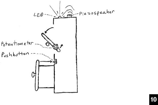
Let’s say you have a cabinet with a door on a hinge and a drawer, and it needs a very small alarm system. Or maybe you want to design a special cabinet with built-in security. Figure 10-1 shows a sketch of how a potentiometer and electrical contact similar to a pushbutton could be used to detect when either the door or drawer is open. This sketch is similar to a concept diagram, which focuses only on conveying what the product or invention does.
Prototyping Your Own Inventions · Page 309
Figure 10-1
Concept
Sketch of a
Cabinet Micro
Security
System
The functional description is important. When you have a better idea of what your device is supposed to do at the beginning, it prevents problems that can happen if you have to redesign the device to accommodate something you didn’t think about. Designers and companies that create custom devices for customers have to be very careful to crossexamine their customers to understand what they expect. Especially for customengineered devices, redesigns can be hugely expensive and time consuming.
Here is an example of a very brief functional description we can use for our simple system: Develop a circuit and program prototype for a micro alarm system that can monitor one small door that’s on a hinge and a drawer. If armed, an alarm should sound if either door or drawer is opened. A status LED should glow green when the alarm is not armed, and red when it is armed. A prototype may be armed and disarmed by computer control. A time delay should be incorporated after the device has been armed to allow the user to close the cabinet.
Page 310 · What’s a Microcontroller?
Specification
Beyond the functional description, a specification typically accounts for as many aspects of the proposed device as possible, including: cost, power consumption, voltage supply, dimensions, weight, speaker volume, and many other details.
Initial Design
Often, the initial design involves brainstorming for approaches that “might” solve the design problem, and many of these ideas have to be tested to find out if they really are feasible. Other portions of the design might involve fairly standard or common parts and design practices. Our micro alarm fits in this category, at least for the prototype. A pushbutton could be mounted in the cabinet so that when the drawer is closed, it presses the pushbutton. For the door on a hinge, a potentiometer could be attached so that it twists with the door and can sense the door’s position. The bicolor LED is a familiar indicator, and the piezospeaker is certainly a well-known alarm noise maker.
So, now we know the circuits we need for our micro security cabinet prototype: bicolor LED, pushbutton, potentiometer, and piezospeaker. Here is a list of chapters and activities where each of these circuits was introduced:
•Bicolor LED: Chapter 2, Activity #5
•Pushbutton: Chapter 3, Activity #2
•Potentiometer: Chapter 5, Activity #3
•Piezospeaker: Chapter 8, Activity #1
Cabinet Alarm Parts List:
Going back into each chapter and putting all the parts together results in this parts list:
(3) |
Resistors – 220 Ω (red-red-brown) |
(1) |
Piezospeaker |
(1) |
Resistors – 10 kΩ (brown-black-orange) |
(1) |
Capacitor – 0.01 µF |
(1) |
LED – bicolor |
(1) |
Potentiometer – 10 kΩ |
(1) |
Pushbutton – normally open |
(4) |
Jumper wires |
Cabinet Alarm Schematic
The schematic in Figure 10-2 is arranged to give all the components plenty of space on the breadboard, so not all the I/O pin connections are the same as they were in earlier chapters. You’ll have to keep this in mind when you harvest code examples from the earlier chapters to test each of the circuits.