

Whats A Microcontroller v3
.0.pdf1 |
4 |
6 |
E |
C |
B |
7 |
9 |
A |
F |
10 |
5 |
G |
DP |
|
LED’s |
3 |
8 |
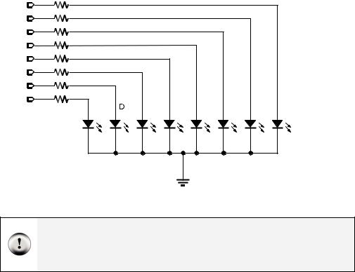
Digital Display · Page 171
Figure 6-3
7-Segment LED Display
Schematic
ACTIVITY #1: BUILDING AND TESTING THE 7-SEGMENT LED DISPLAY
In this activity, you will manually build circuits to test each segment in the display.
7-Segment LED Display Test Parts
(1) 7-segment LED display
(5) Resistors – 1 kΩ (brown-black-red)
(1) Jumper wire
7-Segment LED Display Test Circuits
9With power disconnected from your Board of Education or HomeWork Board, build the circuit shown in Figure 6-4 and Figure 6-5.
9Reconnect power and verify that the A segment emits light.
What’s the x with the nc above it in the schematic? The nc stands for not connected or no-connect. It indicates that a particular pin on the 7-segment LED display is not connected to anything. The x at the end of the pin also means not connected. Schematics sometimes use just the x or just the nc.
Page 172 · What’s a Microcontroller?
Vdd


 1 kΩ
1 kΩ
nc |
nc |
nc |
nc |
|
nc |
nc |
nc |
X |
X |
X |
X |
|
X |
X |
X |
1 |
|
4 |
6 |
7 |
9 |
10 |
5 |
E |
|
C |
B |
A |
F |
G |
DP |
|
|
|
|
|
|
|
LED’s |
|
|
3 |
|
|
8 |
|
|
|
X |
|
Vss |
nc |
|
|
|
|
|
P0 P1 P2 P3 P4 P5 P6 P7 P8 P9 P1 P1 P1 P1 P1 P1 X 0 1 2 3 4 5 2 |
X3 |
|
|
Vdd |
|
|
Vin |
|
|
Vss |
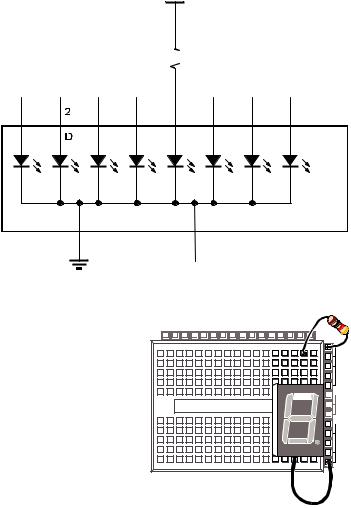
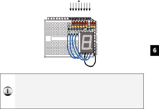
Figure 6-4
Test Circuit Schematic for the “A” Segment LED Display
Figure 6-5
Test Circuit Wiring Diagram for the “A” Segment LED Display
9Disconnect power, and modify the circuit by connecting the resistor to the B LED input as shown in Figure 6-6 and Figure 6-7.
Digital Display · Page 173
Vdd


 1 kΩ
1 kΩ
nc |
nc |
nc |
|
nc |
nc |
nc |
nc |
X |
X |
X |
|
X |
X |
X |
X |
1 |
|
4 |
6 |
7 |
9 |
10 |
5 |
E |
|
C |
B |
A |
F |
G |
DP |
|
|
|
|
|
|
|
LED’s |
|
|
3 |
|
|
8 |
|
|
|
|
|
|
|
|
X |
|
|
|
|
|
|
|
||
|
|
|
|
|
|
nc |
|
Vss |
|||||||
|
|||||||
P0 P1 P2 P3 P4 P5 P6 P7 P8 P9 P1 P1 P1 P1 P1 P1 X 0 1 2 3 4 5 2 |
X3 |
|
Vdd |
|
Vin |
|
Vss |
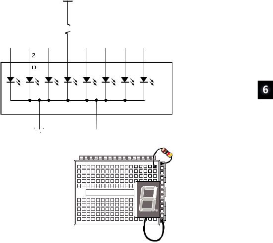
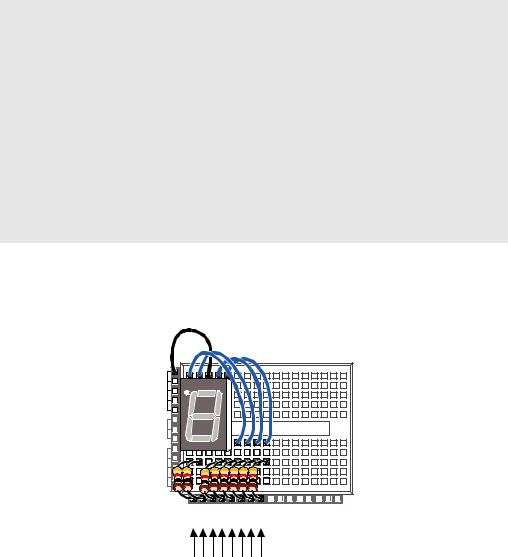
Figure 6-6
Test Circuit Schematic for the ”B” Segment LED Display
Figure 6-7
Test Circuit Wiring Diagram for the “B” Segment LED Display
9Reconnect power and verify that the B segment emits light.
9Using the pin map from Figure 6-2 as a guide, repeat these steps for segments C
through G.
Page 174 · What’s a Microcontroller?
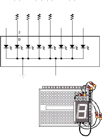
Your Turn – The Number 3 and the Letter H
Figure 6-8 and Figure 6-9 show the digit “3” hardwired into the 7-segment LED display.
Vdd |
Vdd |
Vdd |
Vdd |
Vdd |
|||||||||
|
|
|
|
|
|
|
|
|
|
|
|
|
|
|
|
|
|
|
1 kΩ (all) |
|
nc |
|
|
|
nc |
|
nc |
X |
|
|
|
X |
|
X |
1 |
4 |
6 |
7 |
9 |
10 |
5 |
E |
C |
B |
A |
F |
G |
DP |
|
|
|
|
|
|
LED’s |
3 |
|
|
|
8 |
|
|
|
|
|
|
|
|
X |
|
|
|
|
|
|
|
||
|
|
|
|
|
|
nc |
|
Vss |
|||||||
|
|||||||
P0 P1 P2 P3 P4 P5 P6 P7 P8 P9 P1 P1 P1 P1 P1 P1 X 0 1 2 3 4 5 2 |
X3 |
|
Vdd |
|
Vin |
|
Vss |
Figure 6-8
Hardwired Digit “3”
Figure 6-9
Wiring Diagram for Figure 6-8
9Build and test the circuit shown in Figure 6-8 and Figure 6-9, and verify that it displays the number three.
9Draw a schematic that will display the number 2 on the 7-segment LED.
9Build and test the circuit to make sure it works. Trouble-shoot if necessary.
9Determine the circuit needed for the letter “H” and then build and test it.
Digital Display · Page 175
ACTIVITY #2: CONTROLLING THE 7-SEGMENT LED DISPLAY
In this activity, you will connect the 7-segment LED display to the BASIC Stamp, and then run a simple program to test and make sure each LED is properly connected.
7-Segment LED Display Parts
(1) 7-segment LED display
(8) Resistors – 1 kΩ (brown-black-red)
(5) Jumper wires
Connecting the 7-Segment LED Display to the BASIC Stamp
Figure 6-11 shows the schematic and Figure 6-12 shows the wiring diagram for this BASIC Stamp controlled 7-segment LED display example.
9 Build the circuit shown in Figure 6-11 and Figure 6-12.
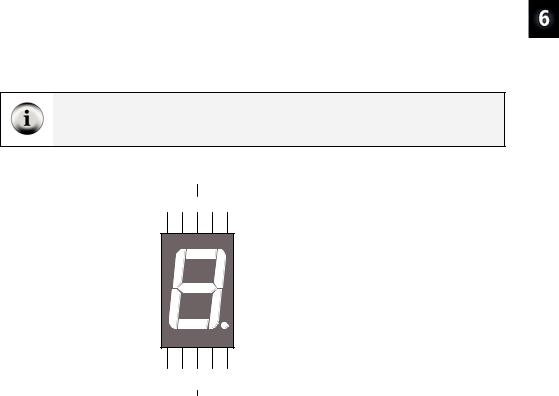
Schematic and pin map: If you are trying to build the circuit from the schematic in Figure 6-11 without relying on Figure 6-12, make sure to consult the 7-segment LED display’s pin map, shown here again in Figure 6-10 for convenience.
|
Common |
|
|
|
Cathode |
|
|
10 9 |
8 7 |
6 |
|
G |
F |
A |
B |
|
|
A |
|
|
F |
B |
|
|
|
G |
|
E |
C |
|
|
|
|
D |
|
E |
D |
C |
DP |
1 2 |
3 4 |
5 |
|
|
Common |
|
|
|
Cathode |
|
|
Figure 6-10
7-Segment LED Display Part
Drawing and Pin Map
Page 176 · What’s a Microcontroller? |
|
|
|
|
|
|
1 kΩ |
|
|
|
|
|
|
(All) |
|
|
|
|
|
|
P15 |
|
|
|
|
|
|
P14 |
|
|
|
|
|
|
P13 |
|
|
|
|
|
|
P12 |
|
|
|
|
|
|
P11 |
|
|
|
|
|
|
P10 |
|
|
|
|
|
|
P9 |
|
|
|
|
|
|
P8 |
|
DP |
G |
F |
|
|
E |
C |
A |
B |
|||
LED’s |
|
|
|
|
|
|
|
|
|
common |
|
|
|
|
|
Vss |
|
|
|
|
Figure 6-11
BASIC Stamp
Controlled 7-
Segment
LED Display
Schematic
Be careful with the resistors connected to P13 and P14. Look closely at the resistors connected to P13 and P14 in Figure 6-12. There is gap between these two resistors. The gap is shown because pin 8 on the 7-segment LED display is left unconnected. A resistor connects I/O pin P13 to 7-segment LED display pin 9. Another resistor connects P14 to 7-segment LED display pin 7.
Digital Display · Page 177
DP |
|
E D C G F A B |
|
P0 P1 P2 P3 P4 P5 P6 P7 P8 P9 P1 P1 P1 P1 P1 P1 X 0 1 2 3 4 5 2 |
X3 |
|
Vdd |
|
Vin |
|
Vss |
Figure 6-12
Wiring Diagram for Figure 6-11
Use the segment letters above this diagram as a reference.
Parallel Device: The 7-segment LED display is called a parallel device because the BASIC Stamp has to use a group of I/O lines to send data (high and low information) to the device. In the case of this 7-segment LED display, it takes 8 I/O pins to instruct the device what to display.
Parallel Bus: The wires that transmit the HIGH/LOW signals from the BASIC Stamp to the 7-segment LED display are called a parallel bus. Note that these wires are drawn as parallel lines in Figure 6-11. The term “parallel” kind of makes sense given the geometry of the schematic.
Programming the 7-Segment LED Display Test
The HIGH and LOW commands will accept a variable as a Pin argument. To test each segment, one at a time, simply place the HIGH and LOW commands in a FOR...NEXT loop, and use the index to set the I/O pin high, then low again.
9Enter and run SegmentTestWithHighLow.bs2.
9Verify that every segment in the 7-segement LED display lights briefly, turning on and then off again.
9Record a list of which segment each I/O pin controls.

Page 178 · What’s a Microcontroller?
Example Program: SegmentTestWithHighLow.bs2
'What's a Microcontroller - SegmentTestWithHighLow.bs2
'Individually test each segment in a 7-Segment LED display.
'{$STAMP BS2} '{$PBASIC 2.5}
pinCounter |
VAR |
Nib |
||
PAUSE |
1000 |
|
CR, |
|
DEBUG |
"I/O Pin", |
|||
|
"-------", |
CR |
|
|
FOR pinCounter = |
8 |
TO 15 |
||
DEBUG DEC2 pinCounter, CR |
||||
HIGH pinCounter |
|
|
||
PAUSE 1000 |
|
|
|
|
LOW |
pinCounter |
|
|
|
NEXT
Your Turn – A Different Pattern
Removing the command LOW pinCounter will have an interesting effect:
9Comment the LOW pinCounter command by adding an apostrophe to the left of it.
9Run the modified program and observe the effect.
ACTIVITY #3: DISPLAYING DIGITS
If you include the decimal point there are eight different BASIC Stamp I/O pins that send high/low signals to the 7-segment LED display. That’s eight different HIGH or LOW commands just to display one number. If you want to count from zero to nine, that would be a huge amount of programming. Fortunately, there are special variables you can use to set the high and low values for groups of I/O pins.
In this activity, you will use 8-digit binary numbers instead of HIGH and LOW commands to control the high/low signals sent by BASIC Stamp I/O pins. By setting special variables called DIRH and OUTH equal to the binary numbers, you will be able to control the high/low signals sent by all the I/O pins connected to the 7-segment LED display circuit with a single PBASIC command.
Digital Display · Page 179
8 bits: A binary number that has 8 digits is said to have 8 bits. Each bit is a slot where you can store either a 1 or a 0.
A byte is a variable that contains 8 bits. There are 256 different combinations of zeros and ones that you can use to count from 0 to 255 with 8 bits. This is why a byte variable can store a number between 0 and 255.
Parts and Circuit for Displaying Digits
Same as previous activity
Programming On/Off Patterns Using Binary Numbers
In this activity, you will experiment with the variables DIRH and OUTH. DIRH is a variable that controls the direction (input or output) of I/O pins P8 through P15. OUTH controls the high or low signals that each of these I/O pin sends. As you will soon see, OUTH is especially useful because you can use it to set the high/low signals for eight different I/O pins at once with just one command. Here is an example program that shows how these two variables can be used to count from 0 to 9 on the 7-segment LED display without using HIGH and LOW commands:
Example Program: DisplayDigits.bs2
This example program will cycle the 7-Segment LED display through the digits 0 through 9.
9Enter and run DisplayDigits.bs2.
9Verify that the digits 0 through 9 are displayed.
'What's a Microcontroller - DisplayDigits.bs2
'Display the digits 0 through 9 on a 7-segment LED display.
'{$STAMP BS2} '{$PBASIC 2.5}
DEBUG "Program Running!"
OUTH = %00000000 |
' OUTH initialized to low. |
||
DIRH = %11111111 |
' Set P8-P15 to all output-low. |
||
' |
BAFG.CDE |
' Digit: |
|
' 0 |
|||
OUTH = %11100111 |
|||
PAUSE 1000 |
' 1 |
||
OUTH = %10000100 |
|||
PAUSE 1000 |
|
||
Page 180 · What’s a Microcontroller?
OUTH = %11010011 PAUSE 1000
OUTH = %11010110 PAUSE 1000
OUTH = %10110100 PAUSE 1000
OUTH = %01110110 PAUSE 1000
OUTH = %01110111 PAUSE 1000
OUTH = %11000100 PAUSE 1000
OUTH = %11110111 PAUSE 1000
OUTH = %11110110 PAUSE 1000
DIRH = %00000000
END
'2
'3
'4
'5
'6
'7
'8
'9
'I/O pins to input,
'segments off.
How DisplayDigits.bs2 Works
Figure 6-13 shows how you can use the DIRH and OUTH variables to control the direction and state (high/low) of I/O pins P8 through P15.
Vss |
|
Vin |
Figure 6-13 |
|
|
Vdd |
Using DIRH and OUTH |
to set all I/O Pins to |
|
X3 |
Output-Low |
P15 P14 P13 P12 P11 P10 P9 P8 P7 P6 P5 P4 P3 P2 P1 P0 X2 |
OUTH = %00000000
DIRH = %11111111