

Whats A Microcontroller v3
.0.pdfMeasuring Light · Page 241
Exercises
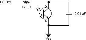
1.Draw the schematic of a phototransistor RC-time circuit connected to P5.
2.Modify TestPhototransistor.bs2 to so that it works on a circuit connected to P5 instead of P2.
3.Explain how you would modify LightMeter.bs2 so that the circular pattern displayed by the 7-segment LED display goes in the opposite direction.
Projects
1.Make a small prototype of a system that automatically closes the blinds when it gets too bright and opens them again when it gets less bright. Use the servo for a mechanical actuator. Hint: For code, you can add two servo control commands to PhototransistorAnalogToBinary.bs2, and change the PAUSE 100 command to
PAUSE 1. Make sure to follow the instructions in the text for calibrating for area light conditions before you test.
2.For extra credit, enhance your solution to Project 1 by incorporating the hysteresis modifications discussed in Activity #5.
Solutions
Q1. Car headlights, streetlights, and outdoor security lights that automatically turn on when it’s dark.
Q2. Laptop displays and cameras with auto exposure.
Q3. 380 nm to 750 nm according to Figure 7-2 on page 197.
Q4. Collector, base, and emitter. The base controls how much current passes into the collector and back out of the emitter.
Q5. Electrically Erasable Programmable Read-Only Memory.
Q6. 2048 bytes. 2048 x 8 = 16,384 bits.
Q7. To store a value – WRITE ; To retrieve a value – READ; The READ command requires a variable.
Q8. A label is a name that can be used as a placeholder in a PBASIC program. Q9. A subroutine is a small segment of code that does a certain job.
Q10. Calling: GOSUB; ending: RETURN
Page 242 · What’s a Microcontroller?
E1. Schematic based on Figure 7-4 on page 200, with P2 changed to P5.
E2. The required changes are very similar to those explained on page 200.
DO
HIGH 5
PAUSE 100
RCTIME 5, 1, time
DEBUG HOME, "time = ", DEC5 time
LOOP
E3. To go in the opposite direction, the patterns must be displayed in the reverse order. This can be done by switching the patterns around inside the LOOKUP statement, or by reversing the order they get looked up. Here are two solutions made with alternative Update_Display subroutines.
Solution 1 |
|
Solution 2 |
|
Update_Display: |
|
Index = 5 '<<Add after Index variable |
|
IF index = 6 THEN index = 0 |
Update_Display: |
|
|
' |
BAFG.CDE |
BAFG.CDE |
|
LOOKUP index, [ |
%01000000, |
' |
|
|
%10000000, |
LOOKUP index, [ |
%01000000, |
|
%00000100, |
|
%10000000, |
|
%00000010, |
|
%00000100, |
|
%00000001, |
|
%00000010, |
OUTH |
%00100000 ], |
|
%00000001, |
1 |
|
%00100000 ], OUTH |
|
index = index + |
IF (index = 0) THEN |
||
RETURN |
|
index = 5 |
|
|
|
ELSE |
- 1 |
|
|
index = index |
|
|
|
ENDIF |
|
|
|
RETURN |
|

Measuring Light · Page 243
P1. Phototransistor from Figure 7-4 on page 200, servo schematic for your board from Chapter 4, Activity #1.
'What's a Microcontroller - Ch07Prj01_Blinds_Control.bs2
'Control servo position with light.
'{$STAMP BS2}
'{$PBASIC 2.5}
valMax |
CON |
4000 |
|
valMin |
CON |
100 |
|
time |
VAR |
Word |
|
PAUSE 1000 |
|
|
|
DO |
|
|
|
HIGH 2 |
|
|
' PAUSE 100 -> PAUSE 1 |
PAUSE 1 |
|
|
|
RCTIME 2, 1, time |
", DEC5 time |
|
|
DEBUG HOME, "time = |
|
||
time = time MAX valMax MIN valMin |
|
||
IF time > (valMax - valMin) / 2 THEN |
' Modify |
||
DEBUG CR, "Open blinds " |
|||
PULSOUT 14, 500 |
|
' Add |
|
ELSE |
|
|
' Modify |
DEBUG CR, "Close blinds" |
|||
PULSOUT 14, 1000 |
|
' Add |
|
ENDIF |
|
|
|
LOOP
P2. Hysteresis functionality added for extra credit:
'What's a Microcontroller - Ch07Prj02_Blinds_Control_Extra.bs2
'Control servo position with light including hysteresis.
'{$STAMP BS2}
'{$PBASIC 2.5}
valMax |
CON |
4000 |
valMin |
CON |
100 |
time |
VAR |
Word |
PAUSE 1000 |
|
|
DO |
|
|

Page 244 · What’s a Microcontroller? |
|
|
|
HIGH 2 |
|
|
' PAUSE 100 -> PAUSE 1 |
PAUSE 1 |
|
|
|
RCTIME 2, 1, time |
= ", DEC5 time |
|
|
DEBUG HOME, |
"time |
|
|
time = time |
MAX valMax MIN valMin |
|
|
IF time > (valMax |
- valMin) / 4 * 3 THEN |
' Modify |
|
DEBUG CR, |
"Open |
blinds " |
|
PULSOUT 14, 500 |
|
' Add |
|
ELSEIF time |
< (valMax - valMin ) / 4 THEN |
' Modify |
|
DEBUG CR, |
"Close blinds" |
||
PULSOUT 14, 1000 |
|
' Add |
|
ENDIF |
|
|
|
LOOP
Frequency and Sound · Page 245
Chapter 8: Frequency and Sound
YOUR DAY AND ELECTRONIC BEEPS
Here are a few examples of beeps you might hear during a normal day: The microwave oven beeps when it’s done cooking your food. The cell phone plays different tones of beeps resembling songs to get your attention when a call is coming in. The ATM machine beeps to remind you not to forget your card. A store cash register beeps to let the teller know that the bar code of the grocery item passed over the scanner was read. Many calculators beep when the wrong keys are pressed. You may have started your day with a beeping alarm clock.
MICROCONTROLLERS, SPEAKERS, AND ON/OFF SIGNALS
Just about all of the electronic beeps you hear during your daily routine are made by microcontrollers connected to speakers. The microcontroller creates these beeps by sending rapid high/low signals to various types of speakers. The rate of these high/low signals is called the frequency, and it determines the tone or pitch of the beep. Each time a high/low repeats itself, it is called a cycle. You will often see the number of cycles per second referred to as hertz, and it is abbreviated Hz. For example, one of the most common frequencies for the beeps that help machines get your attention is 2 kHz. That means that the high/low signals repeat at 2000 times per second.
Introducing the Piezoelectric Speaker
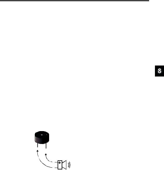
In this activity, you will experiment with sending a variety of signals to a common, small, and inexpensive speaker called a piezoelectric speaker. A piezoelectric speaker is commonly referred to as a piezo speaker or piezo buzzer, and piezo is pronounced “pE- A-zO.” Its schematic symbol and part drawing are shown in Figure 8-1.
Figure 8-1
Piezoelectric Speaker Part Drawing
and Schematic Symbol
Page 246 · What’s a Microcontroller?
ACTIVITY #1: BUILDING AND TESTING THE SPEAKER
In this activity, you will build and test the piezoelectric speaker circuit.
Speaker Circuit Parts
(1)Piezoelectric speaker
(2)Jumper wires
Building the Piezoelectric Speaker Circuit
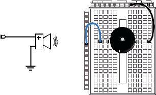
The negative terminal of the piezoelectric speaker should be connected to Vss, and the positive terminal should be connected to an I/O pin. The BASIC Stamp will then be programmed to send high/low signals to the piezoelectric speaker’s positive terminal.
9If your piezo speaker has a sticker on it, just remove it (no washing needed).
9Build the circuit shown in Figure 8-2.
|
Vdd |
Vin |
Vss |
|
X3 |
|
|
|
P15 |
|
|
|
P14 |
|
|
|
P13 |
|
|
|
P12 |
|
|
P9 |
P11 |
+ |
|
P10 |
|
||
|
P9 |
|
|
|
P8 |
|
|
|
P7 |
|
|
|
P6 |
|
|
|
P5 |
|
|
Vss |
P4 |
|
|
P3 |
|
|
|
|
P2 |
|
|
|
P1 |
|
|
|
P0 |
|
|
|
X2 |
|
|
Figure 8-2
Piezoelectric Speaker
Circuit Schematic and
Wiring Diagram
How the Piezoelectric Speaker Circuit Works
When a guitar string vibrates, it causes changes in air pressure. These changes in air pressure are what your ear detects as a tone. The faster the changes in air pressure, the higher the pitch, and the slower the changes in air pressure, the lower the pitch. The element inside the piezo speaker’s plastic case is called a piezoelectric element. When high/low signals are applied to the speaker’s positive terminal, the piezoelectric element vibrates, and it causes changes in air pressure just as a guitar string does. As with the guitar string, your ear detects the changes in air pressure caused by the piezoelectric speaker, and it typically sounds like a beep or a tone.

Frequency and Sound · Page 247
Programming Speaker Control
The FREQOUT command is a convenient way of sending high/low signals to a speaker to make sound. The BASIC Stamp Manual shows the command syntax as this:
FREQOUT Pin, Duration, Freq1 {, Freq2}
As with most of the other commands used in this book, Pin is a value you can use to choose which BASIC Stamp I/O pin to use. The Duration argument is a value that tells the FREQOUT command how long the tone should play, in milliseconds. The Freq1 argument is used to set the frequency of the tone, in hertz. There is an optional Freq2 argument that can be used to play two different tones at the same time.
Here is how to send a tone to I/O pin P9 that lasts for 1.5 seconds and has a frequency of 2 kHz:
FREQOUT 9, 1500, 2000
Example Program: TestPiezoWithFreqout.bs2
This example program sends the 2 kHz tone to the speaker on I/O pin P9 for 1.5 seconds. You can use the Debug Terminal to see when the speaker should be beeping and when it should stop.
9Enter and run TestPiezoWithFreqout.bs2.
9Verify that the speaker makes a clearly audible tone during the time that the Debug Terminal displays the message “Tone sending…”
'What's a Microcontroller - TestPiezoWithFreqout.bs2
'Send a tone to the piezo speaker using the FREQOUT command.
'{$STAMP BS2} '{$PBASIC 2.5}
PAUSE 1000
DEBUG "Tone sending...", CR
FREQOUT 9, 1500, 2000
DEBUG "Tone done."

Page 248 · What’s a Microcontroller?
Your Turn – Adjusting Frequency and Duration
9Save TestPiezoWithFreqout.bs2 under a different name.
9Try some different values for the Duration and Freq1 arguments.
9After each change, run the program and make a note of the effect.
9As the Freq1 argument gets larger, does the tone’s pitch go up or down? Try values of 1500, 2000, 2500 and 3000 to answer this question.
ACTIVITY #2: ACTION SOUNDS
Many toys contain microcontrollers that are used to make “action sounds.” Action sounds tend to involve rapidly changing the frequency played by the speaker. You can also get some interesting effects from playing two different tones together using the FREQOUT command’s optional Freq2 argument. This activity introduces both techniques.
Programming Action Sounds
Action and appliance sounds have three different components:
1.Pause
2.Duration
3.Frequency
The pause is the time between tones, and you can use the PAUSE command to create it. The duration is the amount of time a tone lasts, which you can set using the FREQOUT command’s Duration argument. The frequency determines the pitch of the tone. The higher the frequency, the higher the pitch, the lower the frequency, the lower the pitch. This is, of course, determined by the FREQOUT command’s Freq1 argument.
Example Program: ActionTones.bs2
ActionTones.bs2 demonstrates a few different combinations of pause, duration, and frequency. The first sequence of tones sounds similar to an electronic alarm clock. The second one sounds similar to something a familiar science fiction movie robot might say. The third is more the kind of sound effect you might hear in an old video game.
9Enter and run ActionTones.bs2.
'What's a Microcontroller - ActionTones.bs2
'Demonstrate how different combinations of pause, duration, and frequency
'can be used to make sound effects.

Frequency and Sound · Page 249
'{$STAMP |
BS2} |
|
'{$PBASIC 2.5} |
|
|
duration |
VAR |
Word |
frequency |
VAR |
Word |
PAUSE 1000 |
|
|
DEBUG "Alarm...", CR |
|
|
PAUSE |
100 |
|
FREQOUT 9, 500, 1500 |
|
|
PAUSE |
500 |
|
FREQOUT 9, 500, 1500 |
|
|
PAUSE |
500 |
|
FREQOUT 9, 500, 1500 |
|
|
PAUSE |
500 |
|
FREQOUT 9, 500, 1500 |
|
|
PAUSE |
500 |
|
DEBUG "Robot reply...", CR
PAUSE 100
FREQOUT 9, 100, 2800
FREQOUT 9, 200, 2400
FREQOUT 9, 140, 4200
FREQOUT 9, 30, 2000
PAUSE 500
DEBUG "Hyperspace...", CR
PAUSE 100
FOR duration = 15 TO 1 STEP 1
FOR frequency = 2000 TO 2500 STEP 20
FREQOUT 9, duration, frequency
NEXT
NEXT
DEBUG "Done", CR
END
How ActionTones.bs2 Works
The “Alarm” routine sounds like an alarm clock. This routine plays tones at a fixed frequency of 1.5 kHz for duration of 0.5 s with fixed delays between tones of 0.5 s. The “Robot reply” routine uses various frequencies for brief durations.
The “Hyperspace” routine uses no delay, but it varies both the duration and frequency. By using FOR...NEXT loops to rapidly change the frequency and duration variables, you can get some interesting sound effects. When one FOR...NEXT loop executes inside another one, it is called a nested loop. Here is how the nested FOR...NEXT loop shown

Page 250 · What’s a Microcontroller?
below works. The duration variable starts at 15, then the FOR frequency... loop takes over and sends frequencies of 2000, then 2020, then 2040, and so on, up through 2500 to the piezo speaker. When the FOR frequency... loop is finished, the FOR duration... loop has only repeated one of its 15 passes. So it subtracts 1 from the value of duration and repeats the FOR frequency... loop all over again.
FOR duration = 15 TO 1
FOR frequency = 2000 TO 2500 STEP 15
FREQOUT 9, duration, frequency
NEXT
NEXT
Example Program: NestedLoops.bs2
To better understand how nested FOR...NEXT loops work, NestedLoops.bs2 uses the DEBUG command to show the value of a much less complicated version of the nested loop used in ActionTones.bs2.
9Enter and run NestedLoops.bs2.
9Examine the Debug Terminal output and verify how the duration and frequency variables change each time through the loop.
'What's a Microcontroller - NestedLoops.bs2
'Demonstrate how the nested loop in ActionTones.bs2 works.
'{$STAMP BS2} '{$PBASIC 2.5}
duration |
VAR |
Word |
|
frequency |
VAR |
Word |
|
PAUSE |
1000 |
|
|
DEBUG |
"Duration |
|
Frequency", CR, |
|
"-------- |
|
---------", CR |
FOR duration = 4000 TO 1000 STEP 1000 FOR frequency = 1000 TO 3000 STEP 500
DEBUG " " , DEC5 duration,
" ", DEC5 frequency, CR FREQOUT 9, duration, frequency
NEXT DEBUG CR
NEXT
END