

Whats A Microcontroller v3
.0.pdfMeasuring Rotation · Page 161
These CON directives are just about always declared near the beginning of the program so that they are easy to find.
Once your constant values have been given names with CON directives, you can use ScaleFactor in place of 185 in your program and Offset in place of 500. For example:
time |
= |
time |
*/ scaleFactor |
' |
Scale by 0.724. |
time |
= |
time |
+ offset |
' |
Offset by 500. |
With the values we assigned to the constant names with CON directives, the commands are really:
time |
= |
time |
*/ 185 |
' |
Scale by 0.724. |
time |
= |
time |
+ 500 |
' |
Offset by 500. |
One important advantage to using constants is that you can change one CON directive, and it updates every instance of that constant name in your program. For example, if you write a large program that uses the ScaleFactor constant in 11 different places, one change to Scale Factor CON…, and all the instances of ScaleFactor in your program will use that updated value for the next program download. So, if you changed
ScaleFactor CON 500 to ScaleFactor CON 510, every command with ScaleFactor will use 510 instead of 500.
You can also give I/O pins names using PIN directives. For example, you can declare a PIN directive for I/O pin P7 like this:
RcPin |
PIN 7 |
There are two places in the previous example program where the number 7 is used to refer to I/O pin P7. The first can now be written as:
HIGH RcPin
The second can be written as:
RCTIME RcPin, 1, time
If you later change your circuit to use different I/O pins, all you have to do is change the value in your PIN directive, and both the HIGH and RCTIME commands will be

Page 162 · What’s a Microcontroller?
automatically updated. Likewise, if you have to recalibrate your scale factor or offset, you can also just change the CON directives at the beginning of the program.
The PIN directive has an additional feature: The PBASIC compiler can detect whether the pin name is used as an input or output, and it substitutes either the I/O pin number for output, or the corresponding input register bit variable for input. For example, you could declare two pin directives, like LedPin PIN 14 and ButtonPin PIN 3. Then, your code can make a statement like IF ButtonPin = 1 THEN HIGH LedPin. The PBASIC compiler converts this to IF IN3 = 1 THEN HIGH 14. The IF ButtonPin = 1… made a comparison, and the PBASIC compiler knows that you are using ButtonPin as an input. So it uses the input register bit IN3 instead of the number 3. Likewise, the PBASIC compiler knows that HIGH LedPin uses the LedPin pin name as the constant value 14 for an output operation, so it substitutes HIGH 14.
Example Program: ControlServoWithPotUsingDirectives.bs2
This program works just like ControlServoWithPot.bs2 but makes use of named constants and I/O pins.
9Enter and run ControlServoWithPotUsingDirectives.bs2.
9Observe how the servo responds to the potentiometer and verify that it behaves the same as ControlServoWithPot.bs2.
'What's a Microcontroller - ControlServoWithPotUsingDirectives.bs2
'Read potentiometer in RC-time circuit using RCTIME command.
'Apply scale factor and offset, then send value to servo.
'{$STAMP BS2}
'{$PBASIC 2.5}
rcPin |
PIN |
7 |
' I/O Pin Definitions |
servoPin |
PIN |
14 |
|
scaleFactor |
CON |
185 |
' Constant Declarations |
offset |
CON |
500 |
|
delay |
CON |
10 |
|
time |
VAR |
Word |
' Variable Declaration |
PAUSE 1000 |
|
|
' Initialization |

|
|
Measuring Rotation · Page 163 |
DO |
|
' Main Routine |
HIGH rcPin |
|
|
|
' RC decay measurement |
|
PAUSE delay |
|
|
RCTIME rcPin, 1, time |
' Scale scaleFactor. |
|
time = time |
*/ scaleFactor |
|
time = time |
+ offset |
' Offset by offset. |
PULSOUT servoPin, time |
' Send pulse to servo. |
|
DEBUG HOME, |
DEC5 time |
' Display adjusted time value. |
LOOP
Your Turn – Updating a PIN Directive
As mentioned earlier, if you connect the RC circuit to a different I/O pin, you can simply change the value of the RcPin PIN directive, and this change automatically reflects in the HIGH RcPin and RCTIME RcPin, 1, time commands.
9Save the example program under a new name.
9Change scaleFactor and offset to the unique values for your RC circuit that you determined in the previous Your Turn section.
9Run the modified program and verify that it works correctly.
9Modify your circuit by moving the RC-time circuit connection from I/O pin P7 to I/O pin P8.
9Modify the rcPin declaration so that it reads:
rcPin |
PIN 8 |
9Re-run the program and verify that the HIGH and RCTIME commands are still functioning properly on the different I/O pin with just one change to the RcPin PIN directive.
Page 164 · What’s a Microcontroller?
SUMMARY
This chapter introduced the potentiometer, a part often found under various knobs and dials. The potentiometer has a resistive element that typically connects its outer two terminals and a wiper terminal that contacts a variable point on the resistive element. The potentiometer can be used as a variable resistor if the wiper terminal and one of the two outer terminals is used in a circuit.
The capacitor was also introduced in this chapter. A capacitor can be used to store and release charge. The amount of charge a capacitor can store is related to its value, which is measured in farads, (F). The symbol µ is engineering notation for micro, and it means one-millionth. The capacitors used in this chapter’s activities ranged from 0.01 to 3300 µF.
A resistor and a capacitor can be connected together in a circuit that takes a certain amount of time to charge and discharge. This circuit is commonly referred to as an RCtime circuit. The R and C in RC-time stand for resistor and capacitor. When one value (C in this chapter’s activities) is held constant, the change in the time it takes for the circuit to discharge is related to the value of R. When the value of R changes, the value of the time it takes for the circuit to charge and discharge also changes. The overall time it takes the RC-time circuit to discharge can be scaled by using a capacitor of a different size.
Polling was used to monitor the discharge time of a capacitor in an RC circuit where the value of C was very large. Several different resistors were used to show how the discharge time changes as the value of the resistor in the circuit changes. The RCTIME command was then used to monitor a potentiometer (a variable resistor) in an RC-time circuit with smaller value capacitors. Although these capacitors cause the discharge times to range from roughly 2 to 1500 µs (millionths of a second), the BASIC Stamp has no problem tracking these time measurements with the RCTIME command. The I/O pin must be set HIGH, and then the capacitor in the RC-time circuit must be allowed to charge by using PAUSE before the RCTIME command can be used.
PBASIC programming can be used to measure a resistive sensor such as a potentiometer and scale its value so that it is useful to another device, such as a servo. This involves performing mathematical operations on the measured RC discharge time, which the RCTIME command stores in a variable. This variable can be adjusted by adding a constant value to it, which comes in handy for controlling a servo. In the Projects section, you may find yourself using multiplication and division as well.

Measuring Rotation · Page 165
The CON directive can be used at the beginning of a program to substitute a name for a constant value (a number). After a constant is named, the name can be used in place of the number throughout the program. This can come in handy, especially if you need to use the same number in 2, 3, or even 100 different places in the program. You can change the number in the CON directive, and all 2, 3, or even 100 different instances of that number are automatically updated next time you run the program. PIN directives allow you to name I/O pins. The I/O pin name is context sensitive, so the PBASIC compiler substitutes the corresponding I/O pin number for a pin name in commands like HIGH, LOW, and RCTIME. If the pin name gets used in a conditional statement, it instead substitutes the corresponding input register, like IN2, IN3, etc.
Questions
1.When you turn the dial or knob on a sound system, what component are you most likely adjusting?
2.In a typical potentiometer, is the resistance between the two outer terminals adjustable?
3.How is a capacitor like a rechargeable battery? How is it different?
4.What can you do with an RC-time circuit to give you an indication of the value of a variable resistor?
5.What happens to the RC discharge time as the value of R (the resistor) gets larger or smaller?
6.What does the CON directive do? Explain this in terms of a name and a number.
Exercise
1.Let’s say that you have a 0.5 µF capacitor in an RC timer circuit, and you want the measurement to take 10 times as long. Calculate the value of the new capacitor.
Projects
1.Add a bicolor LED circuit to Activity #4. Modify the example program so that the bicolor LED is red when the servo is rotating counterclockwise, green when the servo is rotating clockwise, and off when the servo holding its position.
2.Use IF...THEN to modify the first example program from Activity #4 so that the servo only rotates between PULSOUT values of 650 and 850.

Page 166 · What’s a Microcontroller?
Solutions
Q1. A potentiometer.
Q2. No, it’s fixed. The variable resistance is between either outer terminal and the wiper (middle) terminal.
Q3. A capacitor is like a rechargeable battery in that it can be charged up to hold voltage. The difference is that it only holds a charge for a very small amount of time.
Q4. You can measure the time it takes for the capacitor to discharge (or charge). This time is related to the resistance and capacitance. If the capacitance is known and the resistance is variable, then the discharge time gives an indication of the resistance.
Q5. As R gets larger, the RC discharge time increases in direct proportion to the increase in R. As R gets smaller, the RC discharge time decreases in direct proportion to the decrease in R.
Q6. The CON directive substitutes a name for a number.
E1. New cap = (10 x old cap value) = (10 x 0.5µF) = 5 µF P1. Activity #4 with bicolor LED added.
P13 |
|
1 |
Potentiometer schematic from Figure 5-11 |
|
|
|
on page 151, servo from Chapter 4, |
|
Activity #1, and bicolor LED from Figure |
2 |
2-19 on page 53 with P15 and P14 changed |
P12 |
to P13 and P12 as shown. |
470Ω
'What's a Microcontroller - Ch5Prj01_ControlServoWithPot.bs2
'Read potentiometer in RC-time circuit using RCTIME command.
'The time var ranges from 126 to 713, and an offset of 330 is needed.
'Bicolor LED on P12, P13 tells direction of servo rotation:
'green for CW, red for CCW, off when servo is holding position.
'{$STAMP BS2}
'{$PBASIC 2.5}
PAUSE 1000 |
Running!" |
|
|
|
DEBUG "Program |
|
|
||
time |
VAR |
Word |
' |
time reading from pot |
prevTime |
VAR |
Word |
' |
previous reading |

|
|
|
Measuring Rotation · Page 167 |
DO |
|
|
|
prevTime |
= time |
' Store previous time reading |
|
HIGH 7 |
|
|
' Read pot using RCTIME |
PAUSE 10 |
|
|
|
RCTIME |
7, 1, time |
' Scale pot, match servo range |
|
time = |
time + 350 |
||
IF ( time > prevTime + 2) THEN |
' increased, pot turned CCW |
||
HIGH |
13 |
|
' Bicolor LED red |
LOW 12 |
time < prevTime - 2) THEN |
' value decreased, pot turned CW |
|
ELSEIF |
( |
||
LOW 13 |
|
' Bicolor LED green |
|
HIGH |
12 |
|
' Servo holding position |
ELSE |
|
|
|
LOW 13 |
|
' LED off |
|
LOW 12
ENDIF
PULSOUT 14, time
LOOP
P2. The key is to add IF...THEN blocks; an example is shown below. CLREOL is a handy DEBUG control character meaning “clear to end of line.”
'What's a Microcontroller - Ch5Prj02_ControlServoWithPot.bs2
'Read potentiometer in RC-time circuit using RCTIME command.
'Modify with IF…THEN so the servo only rotates from 650 to 850.
'The time variable ranges from 1 to 691, so an offset of at least
'649 is needed.
'{$STAMP BS2}
'{$PBASIC 2.5}
PAUSE 1000
DEBUG "Program Running!"
time VAR Word
DO
HIGH 7 |
|
|
' Read pot with RCTIME |
PAUSE 10 |
|
|
|
RCTIME |
7, 1, time |
' Scale time to servo range |
|
time = |
time + 649 |
||
IF (time |
< 650) THEN |
' Constrain range from 650 to 850 |
|
time |
= |
650 |
|
ENDIF |
|
|
|

Page 168 · What’s a Microcontroller?
IF (time > 850) THEN time = 850
ENDIF
PULSOUT 14, time
DEBUG HOME, "time = ", DEC4 time, CLREOL
LOOP

Digital Display · Page 169
Chapter 6: Digital Display
THE EVERYDAY DIGITAL DISPLAY
Figure 6-1 shows a display on the front of an oven door. When the oven is not in use, it displays the time. When the oven is in use, it displays the oven’s timer, cooking settings, and it flashes on and off at the same time an alarm sounds to let you know the food is done. A microcontroller inside the oven door monitors the pushbuttons and updates the display. It also monitors sensors inside the oven and switches devices that turn the heating elements on and off.
Figure 6-1
Digital Clock 7-Segment
Display on Oven Door
Each of the three digits in Figure 6-1 is called a 7-segment display. In this chapter, you will program the BASIC Stamp to display numbers and letters on a 7-segment display.
WHAT’S A 7-SEGMENT DISPLAY?
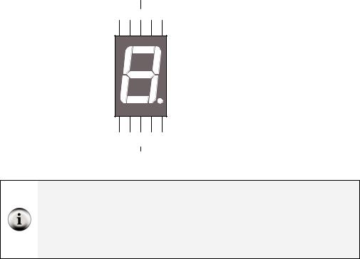
A 7-segment display is rectangular block of 7 lines of equal length that can be lit selectively with LEDS to display digits and some letters. Figure 6-2 shows a part drawing of the 7-segment LED display you will use in this chapter’s activities. It also has a dot that can be used as a decimal point. Each of the segments (A through G) and the dot contain a separate LED, which can be controlled individually. Most of the pins have a number along with a label that corresponds to one of the LED segments. Pin 5 is labeled DP, which stands for decimal point. Pins 3 and 8 are labeled “common cathode” and they will be explained when the schematic for this part is introduced.
Page 170 · What’s a Microcontroller?
|
Common |
|
|
|
Cathode |
|
|
10 9 |
8 7 |
6 |
|
G |
F |
A |
B |
|
|
A |
|
|
F |
B |
|
|
|
G |
|
E |
C |
|
|
|
|
D |
|
E |
D |
C |
DP |
1 2 |
3 4 |
5 |
|
|
Common |
|
|
|
Cathode |
|
|
Figure 6-2
7-Segment LED Display Part
Drawing and Pin Map
Pin Map: Figure 6-2 is an example of a pin map. A pin map contains useful information that helps you connect a part to other circuits. Pin maps usually show a number for each pin, a name for each pin, and a reference.
Take a look at Figure 6-2. Each pin is numbered, and the name for each pin is the segment letter next to the pin. The reference for this part is the decimal point. Orient the part so that the decimal point is at the bottom-right. Then you can see from the pin map that Pin 1 is at the bottom-left, and the pin numbers increase counterclockwise around the case.
Figure 6-3 shows a schematic of the LEDs inside the 7-segment LED display. Each LED anode is connected to an individual pin. All the cathodes are connected together by wires inside the part. Because all the cathodes share a common connection, the 7-segment LED display can be called a common cathode display. By connecting either pin 3 or pin 8 of the part to Vss, you will connect all the LED cathodes to Vss.