

Whats A Microcontroller v3
.0.pdfLights On – Lights Off · Page 41
…right after the compiler directives. It will open the Debug Terminal and keep the COM port open. This will prevent your programs from freezing after one pass through the DO...LOOP, or any of the other looping commands you will be learning in later chapters. You will see this command in some of the example programs that would not otherwise need a DEBUG instruction. So, you should be able to run all of the remaining programs in this book even if your computer failed the diagnostic test, but in that case be sure to add a short DEBUG command when you start writing your own programs.
Your Turn – Timing and Repetitions
By changing the PAUSE command’s Duration argument you can change the amount of time the LED stays on and off. For example, by changing both the Duration arguments to 250, it will cause the LED to flash on and off twice per second. The DO…LOOP in your program will now look like this:
DO
HIGH 14
PAUSE 250
LOW 14
PAUSE 250
LOOP
9Open LedOnOff.bs2 and save a copy of it as LedOnOffYourTurn.bs2.
9Change both of the PAUSE commands’ Duration arguments from 500 to 250, and re-run the program.
If you want to make the LED blink on and off once every three seconds, with the low time twice as long as the high time, you can program the PAUSE command after the HIGH 14 command so that it takes one second using PAUSE 1000. The PAUSE command after the LOW 14 command will have to be PAUSE 2000.
DO
HIGH 14
PAUSE 1000
LOW 14
PAUSE 2000
LOOP
9 Modify and re-run the program using the code snippet above.

Page 42 · What’s a Microcontroller?
A fun experiment is to see how short you can make the pauses and still see that the LED is flashing. When the LED is flashing very fast, but it looks like it’s just on, it’s called persistence of vision.
Here is how to test to see what your persistence of vision threshold is:
9Try modifying both of your PAUSE command’s Duration arguments so that they are 100.
9Re-run your program and check for flicker.
9Reduce both Duration arguments by 5 and try again.
9Keep reducing the Duration arguments until the LED appears to be on all the time with no flicker. It will be dimmer than normal, but it should not appear to flicker.
One last thing to try is to create a one-shot LED flasher. When the program runs, the LED flashes only once. This is a way to look at the functionality of the DO…LOOP. You can temporarily remove the DO…LOOP from the program by placing an apostrophe to the left of both the DO and LOOP keywords as shown below.
'DO
HIGH 14 PAUSE 1000 LOW 14 PAUSE 2000
'LOOP
9Modify and re-run the program using the code snippet above.
9Explain what happened, why did the LED only flash once?
Commenting a line of code: Placing an apostrophe to the left of a command changes it into a comment. This is a useful tool because you don’t actually have to delete the command to see what happens if you remove it from the program. It is much easier to add and remove an apostrophe than it is to delete and re-type the commands.
Lights On – Lights Off · Page 43
ACTIVITY #3: COUNTING AND REPEATING
In the previous activity, the LED circuit either flashed on and off all the time, or it flashed once and then stopped. What if you want the LED to flash on and off ten times? Computers (including the BASIC Stamp) are great at keeping running totals of how many times something happens. Computers can also be programmed to make decisions based on a variety of conditions. In this activity, you will program the BASIC Stamp to stop flashing the LED on and off after ten repetitions.
Counting Parts and Test Circuit
Use the example circuit shown in Figure 2-11 on page 38.
How Many Times?
There are many ways to make the LED blink on and off ten times. The simplest way is to use a FOR...NEXT loop. The FOR...NEXT loop is similar to the DO...LOOP. Although either loop can be used to repeat commands a fixed number of times, FOR...NEXT is easier to use. This is sometimes called a counted or finite loop.
The FOR...NEXT loop depends on a variable to track how many times the LED has blinked on and off. A variable is a word of your choosing that is used to store a value. The next example program chooses the word counter to “count” how many times the LED has been turned on and off.
Picking words for variable names has several rules:
1.The name cannot be a word that is already used by PBASIC. These words are called reserved words, and some examples that you should already be familiar with are DEBUG, PAUSE, HIGH, LOW, DO, and LOOP. You can see the full Reserved Word List in the BASIC Stamp Manual.
2.The name cannot contain a space.
3.Even though the name can contain letters, numbers, or underscores, it must begin with a letter.
4.The name must be less than 33 characters long.
Example Program: LedOnOffTenTimes.bs2
The program LedOnOffTenTimes.bs2 demonstrates how to use a FOR...NEXT loop to blink an LED on and off ten times.
9 Your test circuit from Activity #2 should be built (or rebuilt) and ready to use.

Page 44 · What’s a Microcontroller?
9Enter the LedOnOffTenTimes.bs2 code into the BASIC Stamp Editor.
9Connect power to your Board of Education or HomeWork Board.
9Run the program.
9Verify that the LED flashes on and off ten times.
9Run the program a second time, and verify that the value of counter shown in the Debug Terminal accurately tracks how many times the LED blinked. Hint: instead of clicking Run a second time, you can press and release the Reset button on your Board of Education or HomeWork Board.
'What's a Microcontroller - LedOnOffTenTimes.bs2
'Turn an LED on and off. Repeat 10 times.
'{$STAMP BS2}
'{$PBASIC 2.5}
counter VAR Byte
FOR counter = 1 TO 10
DEBUG ? counter
HIGH 14
PAUSE 500
LOW 14
PAUSE 500
NEXT
DEBUG "All done!"
END
How LedOnOffTenTimes.bs2 Works
This PBASIC statement:
counter VAR Byte
…tells the BASIC Stamp Editor that your program will use the word counter as a variable that can store a byte’s worth of information.
Lights On – Lights Off · Page 45
What’s a Byte? A byte is enough memory to store a number between 0 and 255. The BASIC Stamp has four different types of variables, and each can store a different range of numbers:
Table 2-2: Variable Types and Values they can Store
Variable type |
Range of Values |
Bit |
0 to 1 |
Nib |
0 to 15 |
Byte |
0 to 255 |
Word |
0 to 65535 |
|
|
A DEBUG instruction can include formatters that determine how information should be displayed in the Debug Terminal. Placing the “?”question mark formatter before a variable in a DEBUG command tells the Debug Terminal to display the name of the variable and its value. This is how the command:
DEBUG ? counter
…displays both the name and the value of the counter variable in the Debug Terminal.
The FOR...NEXT loop and all the commands inside it are shown below. The statement FOR counter = 1 to 10 tells the BASIC Stamp that it will have to set the counter variable to 1, then keep executing commands until it gets to the NEXT statement. When the BASIC Stamp gets to the NEXT statement, it jumps back to the FOR statement. The FOR statement adds one to the value of counter. Then, it checks to see if counter is greater than ten yet. If not, it repeats the process. When the value of counter finally reaches eleven, the program skips the commands between the FOR and NEXT statements and moves on to the command that comes after the NEXT statement.
FOR counter = 1 to 10
DEBUG ? counter
HIGH 14
PAUSE 500
LOW 14
PAUSE 500
NEXT
Page 46 · What’s a Microcontroller?
The command that comes after the NEXT statement is:
DEBUG "All done!"
This command is included just to show what the program does after ten times through the FOR...NEXT loop. It moves on to the command that comes after the NEXT statement.
Your Turn – Other Ways to Count
9 In the program LedOnOffTenTimes.bs2, replace the statement:
FOR counter = 1 to 10 |
with this: |
FOR counter = 1 to 20 |
9Re-run the program. What did the program do differently, and was this expected?
9Try a second modification to the FOR statement. This time, change it to:
FOR counter = 20 to 120 STEP 10
How many times did the LED flash? What values displayed in the Debug Terminal?
ACTIVITY #4: BUILDING AND TESTING A SECOND LED CIRCUIT
Indicator LEDs can be used to tell the machine’s user many things. Many devices need two, three, or more LEDs to tell the user if the machine is ready or not, if there is a malfunction, if it’s done with a task, and so on.
In this activity, you will repeat the LED circuit test in Activity #1 for a second LED circuit. Then you will adjust the example program from Activity #2 to make sure the LED circuit is properly connected to the BASIC Stamp. After that, you will modify the example program from Activity #2 to make the LEDs operate in tandem.
Extra Parts Required
In addition to the parts you used in Activities 1 and 2, you will need these parts:
(1) LED – yellow
(1) Resistor – 470 Ω (yellow-violet-brown)
Lights On – Lights Off · Page 47
Building and Testing the Second LED Circuit
In Activity #1, you manually tested the first LED circuit to make sure it worked before connecting it to the BASIC Stamp. Before connecting the second LED circuit to the BASIC Stamp, it’s important to test it too.
9Disconnect power from your Board of Education or HomeWork Board.
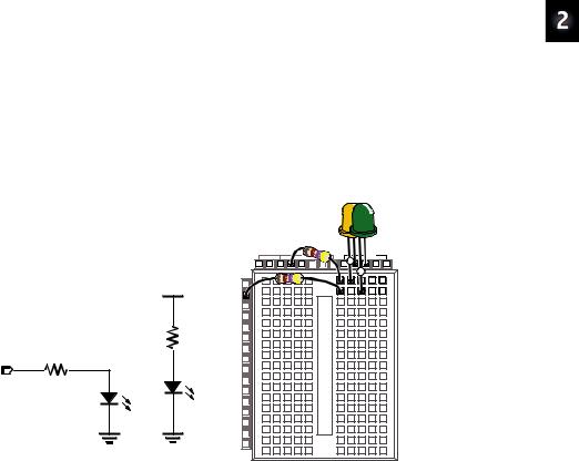
9Construct the second LED circuit as shown in Figure 2-13.
9Reconnect power to your Board of Education or HomeWork Board.
9Did the LED circuit you just added turn on? If yes, then continue. If no, Activity #1 has some trouble-shooting suggestions that you can repeat for this circuit.
|
Vdd |
|
470 Ω |
P14 |
|
470 Ω |
|
|
LED |
Vss |
Vss |
|
Vdd |
Vin |
Vss |
|
X3 |
|
+ |
|
|
+ |
|
|
P15 |
|
|
|
|
|
|
|
P14 |
|
|
|
P13 |
|
|
|
P12 |
|
|
|
P11 |
|
|
|
P10 |
|
|
|
P9 |
|
|
|
P8 |
|
|
|
P7 |
|
|
|
P6 |
|
|
|
P5 |
|
|
LED |
P4 |
|
|
P3 |
|
|
|
|
P2 |
|
|
|
P1 |
|
|
|
P0 |
|
|
|
X2 |
|
|
Figure 2-13
Manual Test Circuit for Second LED
9Disconnect power to your Board of Education or HomeWork Board.
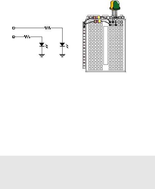
9Modify the second LED circuit you just tested by connecting the LED circuit’s resistor lead (input) to P15 as shown in Figure 2-14.
Page 48 · What’s a Microcontroller?
P15
470 Ω
P14
470 Ω
LED
Vss
|
Vdd |
Vin |
Vss |
|
X3 |
|
+ |
|
|
+ |
|
|
P15 |
|
|
|
|
|
|
|
P14 |
|
|
|
P13 |
|
|
|
P12 |
|
|
|
P11 |
|
|
|
P10 |
|
|
|
P9 |
|
|
|
P8 |
|
|
|
P7 |
|
|
LED |
P5P6 |
|
|
Vss |
P4 |
|
|
P3 |
|
|
|
|
P2 |
|
|
|
P1 |
|
|
|
P0 |
|
|
|
X2 |
|
|
Figure 2-14
Connecting the Second LED to the BASIC Stamp
Schematic (left) and wiring diagram (right).
Using a Program to Test the Second LED Circuit
In Activity #2, you used an example program and the HIGH and LOW commands to control the LED circuit connected to P14. These commands will have to be modified to control the LED circuit connected to P15. Instead of using HIGH 14 and LOW 14, you will use
HIGH 15 and LOW 15.
Example Program: TestSecondLed.bs2
9Enter TestSecondLed.bs2 into the BASIC Stamp Editor.
9Connect power to your Board of Education or HomeWork Board.
9Run TestSecondLED.bs2.
9Make sure the LED circuit connected to P15 is flashing. If the LED connected to P15 flashes, move on to the next example (Controlling Both LEDs). If the LED circuit connected to P15 is not flashing, check your circuit for wiring errors and your program for typing errors and try again.
'What's a Microcontroller - TestSecondLed.bs2
'Turn LED connected to P15 on and off.
'Repeat 1 time per second indefinitely.
'{$STAMP BS2}
'{$PBASIC 2.5}
DEBUG "Program Running!"

Lights On – Lights Off · Page 49
DO
HIGH 15
PAUSE 500
LOW 15
PAUSE 500
LOOP
Controlling Both LEDs
Yes, you can flash both LEDs at once. One way you can do this is to use two HIGH commands before the first PAUSE command. One HIGH command sets P14 high, and the next HIGH command sets P15 high. You will also need two LOW commands to turn both LEDs off. It’s true that both LEDs will not turn on and off at exactly the same time because one is turned on or off after the other. However, there is no more than a millisecond’s difference between the two changes, and the human eye will not detect it.
Example Program: FlashBothLeds.bs2
9Enter the FlashBothLeds.bs2 code into the BASIC Stamp Editor.
9Run the program.
9Verify that both LEDs appear to flash on and off at the same time.
'What's a Microcontroller - FlashBothLeds.bs2
'Turn LEDs connected to P14 and P15 on and off.
'{$STAMP BS2}
'{$PBASIC 2.5}
DEBUG "Program Running!"
DO
HIGH 14
HIGH 15
PAUSE 500
LOW 14
LOW 15
PAUSE 500
LOOP
Page 50 · What’s a Microcontroller?
Your Turn – Alternate LEDs
You can cause the LEDs to alternate by swapping the HIGH and LOW commands that control one of the I/O pins. This means that while one LED is on, the other will be off.
9Modify FlashBothLeds.bs2 so that the commands between the DO and LOOP keywords look like this:
HIGH 14
LOW 15
PAUSE 500
LOW 14
HIGH 15
PAUSE 500
9Run the modified version of FlashBothLeds.bs2 and verify that the LEDs flash alternately on and off.
ACTIVITY #5: USING CURRENT DIRECTION TO CONTROL A BICOLOR LED
The device shown in Figure 2-15 is a security monitor for electronic keys. When an electronic key with the right code is used, the LED changes color, and a door opens. This kind of LED is called a bicolor LED. This activity answers two questions:
1.How does the LED change color?
2.How can you run one with the BASIC Stamp?