

Whats A Microcontroller v3
.0.pdfDigital Input – Pushbuttons · Page 71
Building the Pushbutton and LED Circuits
Figure 3-11 shows the pushbutton circuit used in the activity you just finished along with the LED circuit from Chapter 2, Activity #2.
9 Build the circuit shown in Figure 3-11.
P14 


 470 Ω
470 Ω
LED |
Vdd |
Vin |
Vss |
X3


 +
+
Vss |
P15 |
|
|
P14 |
|
Vdd |
P13 |
|
P12 |
||
|
P11 |
|
|
P10 |
|
|
P9 |
|
|
P8 |
|
P3 |
P7 |
|
P6 |
||
220 Ω |
P5 |
|
P4 |
||
10 kΩ |
||
P3 |
||
|
P2 |
|
|
P1 |
|
Vss |
P0 |
|
X2 |
Figure 3-11
Pushbutton and
LED Circuit
Programming Pushbutton Control
The BASIC Stamp can be programmed to make decisions using an IF...THEN...ELSE statement. The example program you are about to run will flash the LED on and off when the pushbutton is pressed. Each time through the DO...LOOP, the IF...THEN...ELSE statement checks the state of the pushbutton and decides whether or not to flash the LED.
Example Program: PushbuttonControlledLed.bs2
9Enter PushbuttonControlledLed.bs2 into the BASIC Stamp Editor and run it.
9Verify that the LED flashes on and off while the pushbutton is pressed and held down.
9Verify that the LED does not flash when the pushbutton is not pressed down.

Page 72 · What’s a Microcontroller?
'What's a Microcontroller - PushbuttonControlledLed.bs2
'Check pushbutton state 10 times per second and blink LED when pressed.
'{$STAMP BS2}
'{$PBASIC 2.5}
DO
DEBUG ? IN3
IF (IN3 = 1) THEN
HIGH 14
PAUSE 50
LOW 14
PAUSE 50
ELSE
PAUSE 100
ENDIF
LOOP
How PushbuttonControlledLed.bs2 Works
This program is a modified version of ReadPushbuttonState.bs2 from the previous activity. The DO...LOOP and DEBUG ? IN3 commands are the same. The PAUSE 250 was replaced with an IF...THEN...ELSE statement. When the condition after the IF is true (IN3 = 1), the commands that come after the THEN statement are executed. They will be executed until the ELSE statement is reached, at which point the program skips to the ENDIF and moves on. When the condition after the IF is not true (IN3 = 0), the commands after the ELSE statement are executed until the ENDIF is reached.
You can make a detailed list of what a program should do, to either help you plan the program or to describe what it does. This kind of list is called pseudo code, and the example below uses pseudo code to describe how PushbuttonControlledLed.bs2 works.

Digital Input – Pushbuttons · Page 73
• Do the commands between here and the Loop statement over and over again o Display the value of IN3 in the Debug Terminal
oIf the value of IN3 is 1, Then
Turn the LED on
Wait for 1/20 of a second
Turn the LED off
Wait for 1/20 of a second
oElse, (if the value of IN3 is 0)
do nothing, but wait for the same amount of time it would have taken to briefly flash the LED (1/10 of a second).
•Loop
Your Turn – Faster/Slower
9Save the example program under a different name.
9Modify the program so that the LED flashes twice as fast when you press and hold the pushbutton.
9Modify the program so that the LED flashes half as fast when you press and hold the pushbutton.
ACTIVITY #4: TWO PUSHBUTTONS CONTROLLING TWO LED CIRCUITS
Let’s add a second pushbutton to the project and see how it works. To make things a little more interesting, let’s also add a second LED circuit and use the second pushbutton to control it.
Pushbutton and LED Circuit Parts
(2) Pushbuttons – normally open
(2)Resistors – 10 kΩ (brown-black-orange)
(2)Resistors – 470 Ω (yellow-violet-brown)
(2)Resistors – 220 Ω (red-red-brown)
(2)LEDs – any color
(3)Jumper wires

Page 74 · What’s a Microcontroller?
Adding a Pushbutton and LED Circuit
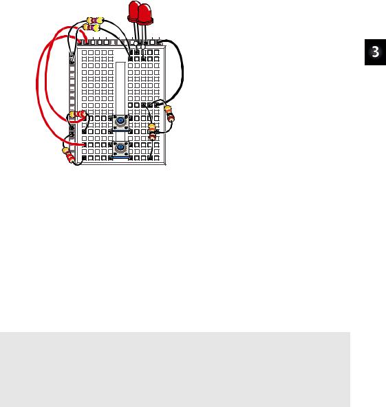
Figure 3-12 shows a second LED and pushbutton circuit added to the circuit you tested in the previous activity.
9Build the circuit shown in Figure 3-12. If you need help building the circuit shown in the schematic, use the wiring diagram in Figure 3-13 as a guide.
9Modify ReadPushbuttonState.bs2 so that it reads IN4 instead of IN3, and use it to test your second pushbutton circuit.
P15 |
|
470 Ω |
|
P14 |
|
470 Ω |
|
LED |
LED |
Vss |
Vss |
Vdd Vdd
P4 |
|
220 Ω |
|
P3 |
|
220 Ω |
|
10 kΩ |
10 kΩ |
Figure 3-12
Schematic for Two Pushbuttons and LEDs
Vss Vss
Dots indicate connections: There are three places where lines intersect in Figure 3-12, but only two of those intersections have dots. When two lines intersect with a dot, it means they are electrically connected. For example, the 10 kΩ resistor on the lower-right side of Figure 3-12 has one of its terminals connected to one of the P3 circuit’s pushbutton terminals and to one of its 220 Ω resistor terminals. When one line crosses another, but there is no dot, it means the two wires DO NOT electrically connect. For example, the line that connects the P4 pushbutton to the 10 kΩ resistor does not connect to the P3 pushbutton circuit because there is no dot at that intersection.
Vdd |
Vin |
Vss |
X3 |
|
+ + |
P15 |
|
|
P14 |
|
|
P13 |
|
|
P12 |
|
|
P11 |
|
|
P10 |
|
|
P9 |
|
|
P8 |
|
|
P7 |
|
|
P6 |
|
|
P5 |
|
|
P4 |
|
|
P3 |
|
|
P2 |
|
|
P1 |
|
|
P0 |
|
|
X2 |
|
|
Digital Input – Pushbuttons · Page 75
Figure 3-13
Wiring Diagram for Two Pushbuttons and LEDs
Programming Pushbutton Control
In the previous activity, you experimented with making decisions using an IF...THEN...ELSE statement. There is also such a thing as an IF...ELSEIF...ELSE statement. It works great for deciding which LED to flash on and off. The next example program shows how it works.
Example Program: PushbuttonControlOfTwoLeds.bs2
9Enter and run PushbuttonControlOfTwoLeds.bs2 in the BASIC Stamp Editor.
9Verify that the LED in the circuit connected to P14 flashes on and off while the pushbutton in the circuit connected to P3 is held down.
9Also check to make sure the LED in the circuit connected to P15 flashes while the pushbutton in the circuit connected to P4 is held down
'What's a Microcontroller - PushbuttonControlOfTwoLeds.bs2
'Blink P14 LED if P3 pushbutton is pressed, and blink P15 LED if
'P4 pushbutton is pressed.
'{$STAMP BS2}
'{$PBASIC 2.5}
PAUSE 1000

Page 76 · What’s a Microcontroller?
DO
DEBUG HOME
DEBUG ? IN4
DEBUG ? IN3
IF (IN3 = 1) THEN
HIGH 14
PAUSE 50
ELSEIF (IN4 = 1) THEN
HIGH 15
PAUSE 50
ELSE
PAUSE 50
ENDIF
LOW 14
LOW 15
PAUSE 50
LOOP
How PushbuttonControlOfTwoLeds.bs2 Works
If the display of IN3 and IN4 scrolled down the Debug Terminal as they did in the previous example, it would be difficult to read. One way to fix this is to always send the cursor to the top-left position in the Debug Terminal using the HOME control character:
DEBUG HOME
By sending the cursor to the home position each time through the DO...LOOP, the commands:
DEBUG ? IN4
DEBUG ? IN3
...display the values of IN4 and IN3 in the same part of the Debug Terminal each time. The DO keyword begins the loop in this program:
DO
These commands in the IF statement are the same as the ones in the example program from the previous activity:

Digital Input – Pushbuttons · Page 77
IF (IN3 = 1) THEN
HIGH 14
PAUSE 50
This is where the ELSEIF keyword helps. If IN3 is not 1, but IN4 is 1, we want to turn the LED connected to P15 on instead of the one connected to P14.
ELSEIF (IN4 = 1) THEN
HIGH 15
PAUSE 50
If neither statement is true, we still want to pause for 50 ms without changing the state of any LED circuits.
ELSE
PAUSE 50
When you’re finished with all the decisions, don’t forget the ENDIF.
ENDIF
It’s time to turn the LEDs off and pause again. You could try to decide which LED you turned on and turn it back off. PBASIC commands execute pretty quickly, so why not just turn them both off and forget about more decision making?
LOW 14
LOW 15
PAUSE 50
The LOOP statement sends the program back up to the DO statement, and the process of checking the pushbuttons and changing the states of the LEDs starts all over again.
LOOP
Your Turn – What about Pressing Both Pushbuttons?
The example program has a flaw. Try pressing both pushbuttons at once, and you’ll see the flaw. You would expect both LEDs to flash on and off, but they don’t because only one code block in an IF...ELSEIF...ELSE statement gets executed before it skips to the ENDIF. Here is how you can fix this problem:

Page 78 · What’s a Microcontroller?
9Save PushbuttonControlOfTwoLeds.bs2 under a new name.
9Replace this IF statement and code block:
IF (IN3 = 1) THEN
HIGH 14
PAUSE 50
...with this IF...ELSEIF statement:
IF (IN3 = 1) AND (IN4 = 1) THEN
HIGH 14
HIGH 15
PAUSE 50
ELSEIF (IN3 = 1) THEN
HIGH 14
PAUSE 50
A code block is a group of commands. The IF statement above has a code block with three commands (HIGH, HIGH, and PAUSE). The ELSEIF statement has a code block with two commands (HIGH, PAUSE).
9Run your modified program and see if it handles both pushbutton and LED circuits as you would expect.
The AND keyword can be used in an condition is true. All conditions with AND
IF...THEN statement to check if more than one have to be true for the IF statement to be true.
The OR keyword can also be used to check if at least one of the conditions are true.
You can also modify the program so that the LED that’s flashing stays on for different amounts of time. For example, you can reduce the Duration of the PAUSE for both pushbuttons to 10, increase the PAUSE for the P14 LED to 100, and increase the PAUSE for the P15 LED to 200.
9Modify the PAUSE commands in the IF and the two ELSEIF statements as discussed.
9Run the modified program.
9Observe the difference in the behavior of each light.

Digital Input – Pushbuttons · Page 79
ACTIVITY #5: REACTION TIMER TEST
You are the embedded systems engineer at a video game company. The marketing department recommends that a circuit to test the player’s reaction time be added to the next hand-held game controller. Your next task is to develop a proof of concept for the reaction timer test.
The solution you will build and test in this activity is an example of how to solve this problem, but it’s definitely not the only solution. Before continuing, take a moment to think about how you would design this reaction timer.
Reaction Timer Game Parts
(1) LED – bicolor
(1)Resistor – 470 Ω (yellow-violet-brown)
(1)Pushbutton – normally open
(1)Resistor – 10 kΩ (brown-black-orange)
(1)Resistor – 220 Ω (red-red-brown)
(2)Jumper wires
Building the Reaction Timer Circuit
Figure 3-14 shows a schematic and wiring diagram for a circuit that can be used with the BASIC Stamp to make a reaction timer game.
9Build the circuit shown in Figure 3-14 on page 80.
9Run TestBiColorLED.bs2 from Chapter 2, Activity #5 to test the bicolor LED circuit and make sure your wiring is correct.
9If you just re-built the pushbutton circuit for this activity, run ReadPushbuttonState.bs2 from Activity #2 in this chapter to make sure your pushbutton is working properly.

Page 80 · What’s a Microcontroller?
P15
1 |
2 |
P14
470 Ω
Vdd
P3
220 Ω

 10 kΩ
10 kΩ
Vss
1 |
2 |
|
|
|
Vdd |
Vin |
Vss |
X3 |
|
|
|
P15 |
|
|
|
P14 |
|
|
|
P13 |
|
|
|
P12 |
|
|
|
P11 |
|
|
|
P10 |
|
|
|
P9 |
|
|
|
P8 |
|
|
|
P7 |
|
|
|
P6 |
|
|
|
P5 |
|
|
|
P4 |
|
|
|
P3 |
|
|
|
P2 |
|
|
|
P1 |
|
|
|
P0 |
|
|
|
X2 |
|
|
|
Figure 3-14
Reaction
Timer Game
Circuit
Programming the Reaction Timer
This next example program will leave the bicolor LED off until the game player presses and holds the pushbutton. When the pushbutton is held down, the LED will turn red for a short period of time. When it turns green, the player has to let go of the pushbutton as fast as he or she can. The program then measures time it takes the player to release the pushbutton in reaction to the light turning green.
The example program also demonstrates how polling and counting work. Polling is the process of checking something over and over again very quickly to see if it has changed. Counting is the process of adding a number to a variable each time something does (or does not) happen. In this program, the BASIC Stamp will poll from the time the bicolor LED turns green until the pushbutton is released. It will wait 1/1000 of a second by using the command PAUSE 1. Each time it polls and the pushbutton is not yet released, it will add 1 to the counting variable named timeCounter. When the pushbutton is released, the program stops polling and sends a message to the Debug Terminal that displays the value of the timeCounter variable.
Example Program: ReactionTimer.bs2
9Enter and run ReactionTimer.bs2.
9Follow the prompts on the Debug Terminal (see Figure 3-15).