

Whats A Microcontroller v3
.0.pdfLights On – Lights Off · Page 51
Figure 2-15
Bicolor LED in a Security
Device
When the door is locked, this bicolor LED glows red. When the door is unlocked by an electronic key with the right code, the LED turns green.
Introducing the Bicolor LED
The bicolor LED’s schematic symbol and part drawing are shown in Figure 2-16.
Figure 2-16
Bicolor LED
Schematic symbol (left) and part drawing (right).
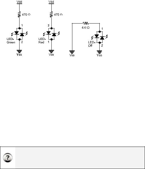
The bicolor LED is really just two LEDs in one package. Figure 2-17 shows how you can apply voltage in one direction and the LED will glow green. By disconnecting the LED and plugging it back in reversed, the LED will then glow red. As with the other LEDs, if you connect both terminals of the circuit to Vss, the LED will not emit light.
Page 52 · What’s a Microcontroller?
Figure 2-17
Bicolor LED and
Applied Voltage
Green (left), red (center) and no light (right)
Bicolor LED Circuit Parts
(1) LED – bicolor
(1) Resistor – 470 Ω (yellow-violet-brown)
(1) Jumper wire
Building and Testing the Bicolor LED Circuit
Figure 2-18 shows the manual test for the bicolor LED.
9Disconnect power from your Board of Education or HomeWork Board.
9Build the circuit shown on the left side of Figure 2-18.
9Reconnect power and verify that the bicolor LED is emitting green light.
9Disconnect power again.
9Modify your circuit so that it matches the right side of Figure 2-18.
9Reconnect power.
9Verify that the bicolor LED is now emitting red light.
9Disconnect power.
What if my bicolor LED’s colors are reversed? Bicolor LEDs are manufactured like the one in Figure 2-16 as well as with the colors reversed. If your bicolor LED glows red when it’s connected in the circuit that should make it glow green and vice-versa, your LED’s colors are reversed. If that’s the case, always plug pin 1 in where the diagrams show pin 2, and pin 2 where the diagrams show pin 1.

Lights On – Lights Off · Page 53
Vdd |
1 Vin |
2 |
Vss |
X3 |
|
|
|
P15 |
|
|
|
P14 |
|
|
|
P13 |
|
|
|
P12 |
|
|
|
P11 |
|
|
|
P10 |
|
|
|
P9 |
|
|
|
P8 |
|
|
|
P7 |
|
|
|
P6 |
|
|
|
P5 |
|
|
|
P4 |
|
|
|
P3 |
|
|
|
P2 |
|
|
|
P1 |
|
|
|
P0 |
|
|
|
X2 |
|
|
|
Vdd |
2 Vin |
1 |
Vss |
X3 |
|
|
|
P15 |
|
|
|
P14 |
|
|
|
P13 |
|
|
|
P12 |
|
|
|
P11 |
|
|
|
P10 |
|
|
|
P9 |
|
|
|
P8 |
|
|
|
P7 |
|
|
|
P6 |
|
|
|
P5 |
|
|
|
P4 |
|
|
|
P3 |
|
|
|
P2 |
|
|
|
P1 |
|
|
|
P0 |
|
|
|
X2 |
|
|
|
Figure 2-18
Manual bicolor LED Test
Bicolor LED green (left) and red (right).
Controlling a bicolor LED with the BASIC Stamp requires two I/O pins. After you have manually verified that the bicolor LED works using the manual test, you can connect the circuit to the BASIC Stamp as shown in Figure 2-19.
9 Connect the bicolor LED circuit to the BASIC Stamp as shown in Figure 2-19.
Figure 2-19
Bicolor LED Connected to BASIC Stamp
Schematic (left) and wiring diagram (right).
Page 54 · What’s a Microcontroller?
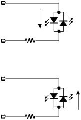
BASIC Stamp Bicolor LED Control
Figure 2-20 shows how you can use P15 and P14 to control the current flow in the bicolor LED circuit. The upper schematic shows how current flows through the green LED when P15 is set to Vdd with HIGH and P14 is set to Vss with LOW. This is because the green LED will let current flow through it when electrical pressure is applied as shown, but the red LED acts like a closed valve and does not let current through it. The bicolor LED glows green.
The lower schematic shows what happens when P15 is set to Vss and P14 is set to Vdd. The electrical pressure is now reversed. The green LED shuts off and does not allow current through. Meanwhile, the red LED turns on, and current passes through the circuit in the opposite direction.
HIGH = Vdd |
P15 |
|
1 |
|
Current |
LOW = Vss |
2 |
P14 |
|
|
470 Ω |
LOW = Vss P15
HIGH = Vdd P14
1
Current
2
470 Ω
Figure 2-20
BASIC Stamp bicolor LED Test
Current through green LED (above) and red LED (below).
Figure 2-20 also shows the key to programming the BASIC Stamp to make the bicolor LED glow two different colors. The upper schematic shows how to make the bicolor LED green using HIGH 15 and LOW 14. The lower schematic shows how to make the bicolor LED glow red by using LOW 15 and HIGH 14. To turn the LED off, send low signals to both P14 and P15 using LOW 15 and LOW 14. In other words, use LOW on both pins.

Lights On – Lights Off · Page 55
The bicolor LED will also turn off if you send high signals to both P14 and P15. Why? Because the electrical pressure (voltage) is the same at P14 and P15 regardless of whether you set both I/O pins high or low.
Example Program: TestBiColorLED.bs2
9Reconnect power.
9Enter and run TestBiColorLed.bs2 code in the BASIC Stamp Editor.
9Verify that the LED cycles through the red, green, and off states.
'What's a Microcontroller - TestBiColorLed.bs2
'Turn bicolor LED red, then green, then off in a loop.
'{$STAMP BS2}
'{$PBASIC 2.5}
PAUSE 1000
DEBUG "Program Running!", CR
DO
DEBUG "Green..."
HIGH 15
LOW 14
PAUSE 1500
DEBUG "Red..."
LOW 15
HIGH 14
PAUSE 1500
DEBUG "Off...", CR
LOW 15
LOW 14
PAUSE 1500
LOOP
Your Turn – Lights Display
In Activity #3, a variable named counter was used to control how many times an LED blinked. What happens if you use the value counter to control the PAUSE command’s Duration argument while repeatedly changing the color of the bicolor LED?
9Rename and save TestBiColorLed.bs2 as TestBiColorLedYourTurn.bs2.
9Add a counter variable declaration before the DO statement:
Page 56 · What’s a Microcontroller?
counter VAR BYTE
9 Replace the test code in the DO...LOOP with this FOR...NEXT loop.
FOR counter = 1 to 50
HIGH 15
LOW 14
PAUSE counter
LOW 15
HIGH 14
PAUSE counter
NEXT
When you are done, your code should look like this:
counter VAR BYTE
DO
FOR counter = 1 to 50
HIGH 15
LOW 14
PAUSE counter
LOW 15
HIGH 14
PAUSE counter
NEXT
LOOP
At the beginning of each pass through the FOR...NEXT loop, the PAUSE value (Duration argument) is only one millisecond. Each time through the FOR...NEXT loop, the pause gets longer by one millisecond at a time until it gets to 50 milliseconds. The DO...LOOP causes the FOR...NEXT loop to execute over and over again.
9 Run the modified program and observe the effect.

Lights On – Lights Off · Page 57
SUMMARY
The BASIC Stamp can be programmed to switch a circuit with a light emitting diode (LED) indicator light on and off. LED indicators are useful in a variety of places including many computer monitors, disk drives, and other devices. The LED was introduced along with a technique to identify its anode and cathode terminals. An LED circuit must have a resistor to limit the current passing through it. Resistors were introduced along with one of the more common coding schemes for indicating a resistor’s value.
The BASIC Stamp switches an LED circuit on and off by internally connecting an I/O pin to either Vdd or Vss. The HIGH command can be used to make the BASIC Stamp internally connect one of its I/O pins to Vdd, and the LOW command can be used to internally connect an I/O pin to Vss. The PAUSE command is used to cause the BASIC Stamp to not execute commands for an amount of time. This was used to make LEDs stay on and/or off for certain amounts of time. The amount of time is determined by the number used in the PAUSE command’s Duration argument.
DO...LOOP can be used to create an infinite loop. The commands between the DO and LOOP keywords will execute over and over again. Even though this is called an infinite loop, the program can still be re-started by disconnecting and reconnecting power or pressing and releasing the Reset button. A new program can also be downloaded to the BASIC Stamp, and this will erase the program with the infinite loop. Counted loops can be made with FOR...NEXT, a variable to keep track of how many repetitions the loop has made, and numbers to specify where to start and stop counting.
Current direction and voltage polarity were introduced using a bicolor LED. If voltage is applied across the LED circuit, current will pass through it in one direction, and it glows a particular color. If the voltage polarity is reversed, current travels through the circuit in the opposite direction and it glows a different color.
Questions
1.What is the name of this Greek letter: Ω, and what measurement does Ω refer to?
2.Which resistor would allow more current through the circuit, a 470 Ω resistor or a 1000 Ω resistor?
3.How do you connect two wires using a breadboard? Can you use a breadboard to connect four wires together?
Page 58 · What’s a Microcontroller?
4.What do you always have to do before modifying a circuit that you built on a breadboard?
5.How long would PAUSE 10000 last?
6.How would you cause the BASIC Stamp to do nothing for an entire minute?
7.What are the different types of variables?
8.Can a byte hold the value 500?
9.What will the command HIGH 7 do?
Exercises
1.Draw the schematic of an LED circuit like the one you worked with in Activity #2, but connect the circuit to P13 instead of P14. Explain how you would modify LedOnOff.bs2 on page 38 so that it will make your LED circuit flash on and off four times per second.
2.Explain how to modify LedOnOffTenTimes.bs2 so that it makes the LED circuit flash on and off 5000 times before it stops. Hint: you will need to modify just two lines of code.
Project
1.Make a 10-second countdown using one yellow LED and one bicolor LED. Make the bicolor LED start out red for 3 seconds. After 3 seconds, change the bicolor LED to green. When the bicolor LED changes to green, flash the yellow LED on and off once every second for ten seconds. When the yellow LED is done flashing, the bicolor LED should switch back to red and stay that way.
Solutions
Q1. Omega refers to the ohm which measures how strongly something resists current flow.
Q2. A 470 Ω resistor: higher values resist more strongly than lower values, therefore lower values allow more current to flow.
Q3. To connect 2 wires, plug the 2 wires into the same 5-socket group. You can connect 4 wires by plugging all 4 wires into the same 5-socket group.
Q4. Disconnect the power.
Q5. 10 seconds.
Q6. PAUSE 60000
Q7. Bit, Nib, Byte, and Word
Q8. No. The largest value a byte can hold is 255. The value 500 is out of range for a byte.
Lights On – Lights Off · Page 59
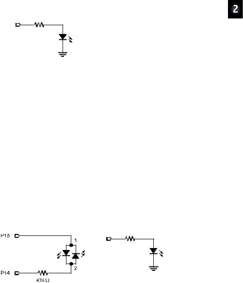
Q9. HIGH 7 will cause the BASIC Stamp to internally connect I/O pin P7 to Vdd. E1. The PAUSE Duration must be reduced to 500 ms / 4 = 125 ms. To use I/O pin
P13, HIGH 14 and LOW 14 have been replaced with HIGH 13 and LOW 13.
P13 |
DO |
470 Ω |
HIGH 13 |
LED |
PAUSE 125 |
|
LOW 13 |
|
PAUSE 125 |
Vss |
LOOP |
E2. The counter variable has to be changed to Word size, and the FOR statement has to be modified to count from 1 to 5000.
counter VAR Word
FOR counter = 1 to 5000 DEBUG ? counter, CR HIGH 14
PAUSE 500 LOW 14 PAUSE 500
NEXT
P1. The bicolor LED schematic, on the left, is unchanged from Figure 2-19 on page 53. The yellow LED schematic is based on Figure 2-11 on page 38. For this project P14 was changed to P13, and a yellow LED was used instead of green. NOTE: When the BASIC Stamp runs out of commands, it goes into a low power mode that causes the bicolor LEDs to flicker briefly every 2.3 seconds. The same applies after the program executes an END command. There’s another command called STOP that you can add to the end of the program to make it hold any high/low signals without going into low power mode, which in turn prevents the flicker.
P13 |
|
470 Ω |
Yellow |
|
|
|
LED |
|
Vss |

Page 60 · What’s a Microcontroller?
'What's a Microcontroller - Ch02Prj01_Countdown.bs2
'10 Second Countdown with Red, Yellow, Green LED
'Red/Green: Bicolor LED on P15, P14. Yellow: P13
'{$STAMP BS2}
'{$PBASIC 2.5}
DEBUG |
"Program Running!" |
|
counter VAR Byte |
|
|
' Red |
for three seconds |
' Bicolor LED Red |
LOW |
15 |
|
HIGH 14 |
|
|
PAUSE 3000 |
|
|
' Green for 10 seconds... |
' Bicolor LED Green |
|
HIGH 15 |
||
LOW |
14 |
|
' ...while the yellow LED is flashing |
|
|
FOR |
counter = 1 TO 10 |
' Yellow LED on |
HIGH 13 |
||
PAUSE 500 |
' Yellow LED off |
|
LOW 13 |
||
PAUSE 500 |
|
|
NEXT |
|
|
' Red |
stays on |
' Bi Color LED Red |
LOW |
15 |
|
HIGH |
14 |
|