

Network Plus 2005 In Depth
.pdf582 Chapter 13 ENSURING INTEGRITY AND AVAILABILITY
NET+ |
As an example, imagine that you work for a data services firm called PayNTime that processes |
3.11payroll checks for a large oil company in the Houston area. Every day, you receive updated payroll information over a T1 link from your client, and every Thursday you compile this information and then cut 2000 checks that you ship overnight to the client’s headquarters. What would happen if the T1 link between PayNTime and the oil company suffered damage in a flood and became unusable on a Thursday morning? How would you ensure that the employees received their pay? If no redundant link to the oil company existed, you would probably need to gather and input the data into your system at least partially by hand. Even then, chances are that you wouldn’t process the payroll checks in time to be shipped overnight.
In this type of situation, you would want a duplicate connection between PayNTime and the oil company’s site for redundancy. You might contract with two different service carriers to ensure the redundancy. Alternatively, you might arrange with one service carrier to provide two different routes. However you provide redundancy in your network topology, you should make sure that the critical data transactions can follow more than one possible path from source to target.
Redundancy in your network offers the advantage of reducing the risk of lost functionality, and potentially lost profits, from a network fault. As you might guess, however, the main disadvantage of redundancy is its cost. If you subscribed to two different service providers for two T1 links in the PayNTime example, you would probably double your monthly leasing costs of approximately $700. Multiply that amount times 12 months, and then times the number of clients for which you need to provide redundancy, and the extra layers of protection quickly become expensive. Redundancy is like a homeowner’s insurance policy: You may never need to use it, but if you don’t get it, the cost when you do need it can be much higher than your premiums. As a general rule, you should invest in connection redundancies where they are absolutely necessary.
Now suppose that PayNTime provides services not only to the oil company, but also to a temporary agency in the Houston area. Both links are critical because both companies need their payroll checks cut each week. To address concerns of capacity and scalability, the company may want to consider partnering with an ISP and establishing secure VPNs (virtual private networks) with its clients. With a VPN, PayNTime could shift the costs of redundancy and network design to the service provider and concentrate on the task it does best—processing payroll. Figure 13-3 illustrates this type of arrangement.
But what about the devices that connect one segment of a LAN or WAN to another? What happens when they experience a fault? Previously, you learned how connectivity devices work and how dedicated lines terminate at a customer’s premises and in a service provider’s data center. Next, you consider how to fundamentally increase the fault tolerance of connectivity devices and a LAN’s or WAN’s connecting links.
To understand how to increase the fault tolerance of not just the topology, but also the network’s connectivity, let’s return to the example of PayNTime. Suppose that the company’s network administrator decides to establish a VPN agreement with a national ISP. PayNTime’s bandwidth analysis indicates that a T1 link is sufficient to transport the data of five customers from the ISP’s office to PayNTime’s data room. Figure 13-4 provides a detailed representation of this arrangement.

FAULT TOLERANCE |
Chapter 13 583 |
NET+
3.11
FIGURE 13-3 VPNs linking multiple customers
FIGURE 13-4 Single T1 connectivity
Notice the many single points of failure in the arrangement depicted in Figure 13-4. As mentioned earlier, the T1 connection could incur a fault. In addition, the firewall, router, CSU/DSU, multiplexer, or switch might suffer faults in their power supplies, NICs, or circuit boards. In a critical component such as a router or switch, the utmost fault tolerance necessitates the use of redundant NICs, power supplies, cooling fans, interfaces, and I/O modules, all of which should ideally be able to immediately assume the duties of an identical component, a capability known as automatic fail-over. Even if one router’s NIC fails, for example, fail-over ensures that the router’s other NIC can automatically handle the first server’s responsibilities.
In cases in which it’s impractical to have fail-over capable components, you can provide some level of fault tolerance by using hot swappable parts. The term hot swappable refers to identical components that can be changed (or swapped) while a machine is still running (hot). A hot swappable component assumes the functions of its counterpart if one suffers a fault. When you purchase switches or routers to support critical links, look for those that contain fail-over

584 Chapter 13 ENSURING INTEGRITY AND AVAILABILITY
NET+ |
capable or hot swappable components. As with other redundancy provisions, these features |
3.11add to the cost of your device purchase.
Purchasing connectivity devices with hot swappable or fail-over capable components does not address all faults that may occur on a connection. Faults may also affect the connecting links. For example, if you connect two offices with a dedicated T1 connection and the T1 cable is severed during a construction mishap, it doesn’t matter whether your router has redundant NICs. The connection will still be down. Because a fault in the T1 link has the same effect as a bad T1 interface in a router, a fully redundant system might be a better option. Such a system is depicted in Figure 13-5.
FIGURE 13-5 Fully redundant T1 connectivity
The preceding scenario utilizes the most reliable option for providing network redundancy for PayNTime. In addition, leasing redundant T1s allows for load balancing, or an automatic distribution of traffic over multiple links or processors to optimize response. Load balancing would maximize the throughput between PayNTime and its ISP, because the aggregate traffic flowing between the two points could move over either T1 link, avoiding potential bottlenecks on a single T1 connection. Although one company might be willing to pay for such complete redundancy, another might prefer a less expensive solution. A less expensive redundancy option might be to use a dial-back WAN link. For example, a company that depends on a Frame Relay WAN might also have an access server with a DSL or dial-up link that automatically connects to the remote site when it detects a failure of the primary link.
Servers
As with other devices, you can make servers more fault-tolerant by supplying them with redundant components. Critical servers (such as those that perform user authentication for an entire LAN, or those that run important, enterprise-wide applications such as an electronic catalog in a library) often contain redundant NICs, processors, and hard disks. These redundant

FAULT TOLERANCE |
Chapter 13 585 |
NET+ |
components provide assurance that if one item fails, the entire system won’t fail; at the same |
3.11time, they enable load balancing.
For example, a server with two 100-Mbps NICs may receive and transmit traffic at a rate of 46 Mbps during a busy time of the day. With additional software provided by either the NIC manufacturer or a third party, the redundant NICs can work in tandem to distribute the load, ensuring that approximately half the data travels through the first NIC and half through the second. This approach improves response time for users accessing the server. If one NIC fails, the other NIC automatically assumes full responsibility for receiving and transmitting all data to and from the server. Although load balancing does not technically fall under the category of fault tolerance, it helps justify the purchase of redundant components that do contribute to fault tolerance.
The following sections describe more sophisticated ways of providing server fault tolerance, beginning with server mirroring.
Server Mirroring
Mirroring is a fault-tolerance technique in which one device or component duplicates the activities of another. In server mirroring, one server continually duplicates the transactions and data storage of another. The servers involved must be identical machines using identical components. As you would expect, mirroring requires a high-speed link between the servers. It also requires software running on both servers that allows them to synchronize their actions continually and, in case of a failure, that permits one server to take over for the other. Server mirroring is considered to be a form of replication, a term that refers to the dynamic copying of data from one location to another.
To illustrate the concept of mirroring, suppose that you give a presentation to a large group of people, and the audience is allowed to interrupt you to ask questions at any time. You might talk for two minutes, wait while someone asked a question, answer the question, begin lecturing again, take another question, and so on. In this sense, you act like a primary server, busily transmitting and receiving information. Now imagine that your identical twin is standing in the next room and can hear you over a loudspeaker. Your twin was instructed to say exactly what you say as quickly as possible after you spoke, but to an empty room containing only a tape recorder. Of course, your twin must listen to you before imitating you. It takes time for the twin to digest everything you say and repeat it, so you must slow down your lecture and your room’s question-and-answer process. A mirrored server acts in much the same way. The time it takes to duplicate the incoming and outgoing data detrimentally affects network performance if the network handles a heavy traffic load. But if you should faint during your lecture, for example, your twin can step into your room and take over for you in very short order. The mirrored server also stands ready to assume the responsibilities of its counterpart.
One advantage to mirroring is that the servers involved can stand side by side or be positioned in different locations—perhaps in two different buildings of a company’s headquarters, or possibly even on opposites sides of a continent. One potential disadvantage to mirroring, however, is the time it takes for a mirrored server to assume the functionality of the failed server. This
586 Chapter 13 ENSURING INTEGRITY AND AVAILABILITY
NET+ delay may last 15 to 90 seconds. Obviously, this downtime makes mirroring imperfect. When
3.11a server fails, users lose network service, and any data in transit at the moment of the failure is susceptible to corruption. Another disadvantage to mirroring is its toll on the network as data is copied between sites.
Makers of server mirroring software include Availl, Legato Systems, LinkPro, and NSI Software. Although such software can be expensive, the hardware costs of mirroring also mount, because one server is devoted to simply acting as a “tape recorder” for all data in case the other server fails. Depending on the potential cost of losing a server’s functionality for any period of time, however, the expense involved may be justifiable.
NOTE
You may be familiar with the term “mirroring” as it refers to Web sites on the Internet. Mirrored Web sites are locations on the Internet that dynamically duplicate other locations on the Internet, to ensure their continual availability. They are similar to, but not necessarily the same as, mirrored servers.
Clustering
Clustering is a fault-tolerance technique that links multiple servers together to act as a single server. In this configuration, clustered servers share processing duties and appear as a single server to users. If one server in the cluster fails, the other servers in the cluster automatically take over its data transaction and storage responsibilities. Because multiple servers can perform services independently of other servers, as well as ensure fault tolerance, clustering is more costeffective than mirroring for large networks.
To understand the concept of clustering, imagine that you and several colleagues (who are not exactly like you) are simultaneously giving separate talks in different rooms in the same conference center. All of your colleagues are constantly aware of your lecture, and vice versa. If you should faint during your lecture, one of your colleagues can immediately jump into your spot and pick up where you left off, without the audience ever noticing. (At the same time, your colleague must continue to present his own lecture, which means that he must split his time between these two tasks.)
To detect failures, clustered servers regularly poll each other on the network, asking, “Are you still there?” They then wait a specified period of time before again asking, “Are you still there?” If they don’t receive a response from one of their counterparts, the clustering software initiates the fail-over. This process may take anywhere from a few seconds to a minute, because all information about a failed server’s shared resources must be gathered by the cluster. Unlike with mirroring, users will not notice the switch. Later, when the other servers in the cluster detect that the missing server has been replaced, they automatically relinquish that server’s responsibilities. The fail-over and recovery processes are transparent to network users.

FAULT TOLERANCE |
Chapter 13 587 |
NET+ |
One disadvantage to clustering is that the clustered servers must be geographically close— |
3.11although the exact distance depends on the clustering software employed. Typically, clustering is implemented among servers located in the same data room. Some clusters can contain servers as far as a mile apart, but clustering software manufacturers recommend a closer proximity. Before implementing a server cluster, you should determine your organization’s fault-tolerance needs and fully research the options available on your servers’ platforms.
Despite its geographic limitations, clustering offers many advantages over mirroring. Each server in the cluster can perform its own data processing; at the same time, it is always ready to take over for a failed server if necessary. Not only does this ability to perform multiple functions reduce the cost of ownership for a cluster of servers, but it also improves performance.
Like mirroring, clustering is implemented through a combination of software and hardware. Novell NetWare 5.x and 6.x and Microsoft Windows Server 2003 incorporate options for server clustering. Clustering has been part of UNIX-type of operating systems since the early 1990s.
Storage
Related to the availability and fault tolerance of servers is the availability and fault tolerance of data storage. In the following sections, you learn about different methods for making sure shared data and applications are never lost or irretrievable.
RAID (Redundant Array of Independent
(or Inexpensive) Disks)
RAID (Redundant Array of Independent (or Inexpensive) Disks) is a collection of disks that provide fault tolerance for shared data and applications. A group of hard disks is called a disk array (or a drive). The collection of disks that work together in a RAID configuration is often referred to as the “RAID drive.” To the system, the multiple disks in a RAID drive appear as a single logical drive. One advantage of using RAID is that a single disk failure will not cause a catastrophic loss of data. Other advantages are increased storage capacity and potentially better disk performance. Although RAID comes in many different forms (or levels), all types use shared, multiple physical or logical hard disks to ensure data integrity and availability.
RAID may be implemented as a hardware or software solution. Hardware RAID includes a set of disks and a separate disk controller. The hardware RAID array is managed exclusively by the RAID disk controller, which is attached to a server through the server’s controller interface (in most cases, a SCSI interface). To the server’s NOS, a hardware RAID array appears as just another storage device.
Software RAID relies on software to implement and control RAID techniques over virtually any type of hard disk (or disks). Software RAID is less expensive overall than hardware RAID, because it does not require special controller or disk array hardware. With today’s fast processors, software RAID performance rivals that of hardware RAID, which was formerly regarded as faster. The software may be a third-party package, or it may exist as part of the NOS. On a

588 Chapter 13 ENSURING INTEGRITY AND AVAILABILITY
NET+ Windows Server 2003 server, for example, RAID drives are configured through the Disk Man-
3.11agement tool. On a NetWare 6.5 server, RAID falls under the NetWare Storage Services component and is managed through the iManager tool. On a Red Hat Linux server, RAID is managed through the Disk Druid tool.
Several different types of RAID are available. The following sections describe the four types that are most common and supported by the latest versions of modern NOSs.
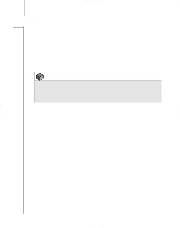
RAID Level 0—Disk Striping
RAID Level 0 (otherwise known as disk striping) is a very simple implementation of RAID in which data is written in 64-KB blocks equally across all disks in the array. Disk striping is not a fault-tolerant method, because if one disk fails, the data contained in it is inaccessible. Thus, RAID Level 0 does not provide true redundancy. Nevertheless, it does use multiple disk partitions effectively, and it improves performance by utilizing multiple disk controllers. The multiple disk controllers allow several instructions to be sent to the disks simultaneously. Of the four types of RAID discussed in this chapter, RAID Level 0 has the best performance.
Figure 13-6 illustrates how data is written to multiple disks in RAID Level 0. Notice how each 64-KB piece of data is written to one discrete area of the disk array. For example, if you saved a 128-KB file, the file would be separated into two pieces and saved in different areas of the drive. Although RAID Level 0 is easy to implement, it should not be used on missioncritical servers because of its lack of fault tolerance.
FIGURE 13-6 RAID Level 0—disk striping
RAID Level 1—Disk Mirroring
RAID Level 1 provides redundancy through a process called disk mirroring, in which data from one disk is copied to another disk automatically as the information is written. Because data is continually saved to multiple locations, disk mirroring provides a dynamic data backup. If one disk in the array fails, the disk array controller automatically switches to the disk that was mirroring the
FAULT TOLERANCE |
Chapter 13 589 |
NET+ |
failed disk. Users do not even notice the failure. After repairing the failed disk, the network admin- |
3.11istrator must perform a resynchronization to return the disk to the array. Because the failed disk’s twin has been saving all of its data while it was out of service, this task is rarely difficult.
The advantages of RAID Level 1 derive from its simplicity and its automatic and complete data redundancy. On the other hand, because it requires two identical disks instead of just one, RAID Level 1 is somewhat costly. In addition, it is not the most efficient means of protecting data, as it usually relies on system software to perform the mirroring, which taxes CPU resources. Figure 13-7 depicts a 128-KB file being written to a disk array using RAID Level 1.
FIGURE 13-7 RAID Level 1—disk mirroring
NOTE
Although they are not covered in this chapter, RAID levels 2, 4, and higher also exist, in addition to RAID installations that combine multiple RAID levels. These versions of RAID are rarely used, however, because they are less reliable, less economical, or less efficient than Levels 0, 1, 3, and 5.
The concept of disk duplexing is related to disk mirroring. In disk duplexing, data is continually copied from one disk to another when it is saved, just as in disk mirroring. In duplexing, however, a separate disk controller is used for each different disk. This provides added fault tolerance, because a disk controller failure will not render data inaccessible. Conversely, if a RAID 1 disk controller fails, all of the data on the storage device becomes inaccessible.
RAID Level 3—Disk Striping with Parity ECC
RAID Level 3 involves disk striping with a special ECC (error correction code), or algorithm used to detect and correct errors, known as parity error correction code. The term parity refers to the mechanism used to verify the integrity of data by making the number of bits in a byte

590 Chapter 13 ENSURING INTEGRITY AND AVAILABILITY
NET+ |
sum to either an odd or even number. To accomplish parity, a parity bit (equal to either 0 or 1) |
3.11is added to the bits’ sum. Table 13-1 expresses how the sums of many bits achieve even parity through a parity bit. Notice that the numbers in the fourth column are all even. If the summed numbers in the fourth column were odd, an odd parity would be used. A system may use either even parity or odd parity, but not both.
Table 13-1 The use of parity bits to achieve parity
Original Data |
Sum of Data Bits |
Parity Bit |
Sum of Data Plus Parity Bits |
01110010 |
4 |
0 |
4 |
00100010 |
2 |
0 |
2 |
00111101 |
5 |
1 |
6 |
10010100 |
3 |
1 |
4 |
|
|
|
|
Parity tracks the integrity of data on a disk. It does not reflect the data type, protocol, transmission method, or file size. A parity bit is assigned to each data byte when it is transmitted or written to a disk. When data is later read from the disk, the data’s bits plus the parity bit are summed again. If the parity does not match (for example, if the end sum is odd but the system uses even parity), then the system assumes that the data has suffered some type of damage. The process of comparing the parity of data read from disk with the type of parity used by the system is known as parity error checking.
In RAID Level 3, parity error checking takes place when data is written across the disk array. If the parity error checking indicates an error, the RAID Level 3 system can automatically correct it. The advantage of using RAID 3 is that it provides a high data transfer rate when reading from or writing to the disks. This quality makes RAID 3 particularly well suited to applications that require high speed in data transfers, such as video editing. A disadvantage of RAID 3 is that the parity information appears on a single disk, which represents a potential single point of failure in the system. Figure 13-8 illustrates how RAID Level 3 works.
FIGURE 13-8 RAID Level 3—disk striping with parity ECC

FAULT TOLERANCE |
Chapter 13 591 |
NET+ RAID Level 5—Disk Striping with Distributed Parity
3.11The highly fault-tolerant RAID Level 5 is the most popular data storage technique in use today. In RAID Level 5, data is written in small blocks across several disks. At the same time, parity error checking information is distributed among the disks. Figure 13-9 depicts two files being written over several disks via RAID Level 5.
|
FIGURE 13-9 RAID Level 5—disk striping with distributed parity |
|
|
RAID Level 5 is similar to, but has several advantages over, RAID Level 3. First, it can write |
|
NET+ |
||
|
3.11data more rapidly because the parity information can be written by any one of the several disk
3.12controllers in the array. Unlike RAID Level 3, RAID Level 5 uses several disks for parity information, making it more fault-tolerant. Also, RAID Level 5 allows you to replace a failed disk with a good one with little interruption of service. This is because, using parity information and the parts of a file that remain on the good disks, RAID controlling software can regenerate the parts of the file that were on the failed disk after that disk is replaced. To take advantage of this feature, some network administrators equip their RAID 5 systems with a hot spare, a disk or partition that is part of the array, but used only in case one of the RAID disks fails. More generally, the term hot spare is used as a synonym for a hot swappable component, which, as you learned earlier, is a duplicate component installed in a device that can assume the original component’s functions in case that component fails. In contrast, cold spare refers to a duplicate component that is not installed, but can be installed in case of a failure. Replacing a component with a cold spare requires an interruption of service.
NET+ NAS (Network Attached Storage)
3.11NAS (network attached storage) is a specialized storage device or group of storage devices that provides centralized fault-tolerant data storage for a network. NAS differs from RAID in that it maintains its own interface to the LAN rather than relying on a server to connect it to the network and control its functions. In fact, you can think of NAS as a unique type of server dedicated to data sharing. The advantage to using NAS over a typical file server is that a NAS device contains its own file system that is optimized for saving and serving files (as opposed to also managing printing, authenticating logon IDs, and so on). Because of this optimization, NAS reads and writes from its disk significantly faster than other types of servers could.