

Cisco. Fundamentals Network Design - Cisco Press
.pdfConfiguring Frame Relay Traffic Shaping
Figure 9-13 Virtual interface configuration example.
interface Ethernet 0
ip address 192.198.78-9 255.255.255.0 ipx network AC
denet cost 4
no mcp enabled
!
interface Serial0 no ip address
encapsulation frame–realy
!
interface Serial0.1 point–to–point
ip address 131.108.3.12.255.255.255.0 frame–relay interface–dlci 21 broadcast no frame–relay inverse–arp IP 21
no frame–relay inverse–arp NOVELL 21
no frame–relay inverse–arp APPLETALK 21 no frame–relay inverse–arp INS 21
!
interface Serial0.2 point–to–point no ip address
decnet cost 10
frame–relay interface–dlci 22 broadcast no frame–relay inverse–arp IP 22
no frame–relay inverse–arp NOVELL 22
no frame–relay inverse–arp APPLETALK 22 no frame–relay inverse–arp INS 22
!
interface Serial0.3 point–to–point no ip address
ipx network A3
frame–relay interface–dlci 23 broadcast no frame–relay inverse–arp IP 23
no frame–relay inverse–arp NOVELL 23
no frame–relay inverse–arp APPLETALK 23 no frame–relay inverse–arp INS 23
!
router igrp 109 network 192.198.78.0
!
ip name–server 255.255.255.255
!
snmp–server community
!
line oon 0 line aux 0 line vty 0 4 end
Subinterface command configuration defining Frame Relay DLCIs and assigning protocols to specific DLCIs
You can use the following commands in Software Release 9.1 to achieve a configuration that is similar to the configuration shown in Figure 9-13:
You can use the following commands in Software Release 9.1 to achieve a configuration that is similar to the configuration shown in Figure 9-13:
Version 9.1 interface serial 0
ip address 131.108.3.12 255.255.255.0 decnet cost 10
novell network A3
frame-relay map IP 131.108.3.62 21 broadcast frame-relay map DECNET 10.3 22 broadcast frame-relay map NOVELL C09845 23 broadcast
Configuring Frame Relay Traffic Shaping
Beginning with Release 11.2, Cisco IOS supports Frame Relay traffic shaping, which provides the following features:
Designing Packet Service Internetworks 9-17

Summary
•Rate enforcement on a per-virtual circuit basis— The peak rate for outbound traffic can be set to the CIR or some other user-configurable rate.
•Dynamic traffic throttling on a per-virtual circuit basis —When BECN packets indicate congestion on the network, the outbound traffic rate is automatically stepped down; when congestion eases, the outbound traffic rate is stepped up again. This feature is enabled by default.
•Enhanced queuing support on a per-virtual circuit basis—Either custom queuing or priority queuing can be configured for individual virtual circuits.
By defining separate virtual circuits for different types of traffic and specifying queuing and an outbound traffic rate for each virtual circuit, you can provide guaranteed bandwidth for each type of traffic. By specifying different traffic rates for different virtual circuits over the same time, you can perform virtual time division multiplexing. By throttling outbound traffic from high-speed lines in central offices to low-speed lines in remote locations, you can ease congestion and data loss in the network; enhanced queuing also prevents congestion-caused data loss. Traffic shaping applies to both PVCs and SVCs.
Summary
This chapter has focused on the implementation of packet-switching services and addresses internetwork design in terms of the packet-switching service topics including hierarchical internetwork design, topology design, broadcast issues, and performance issues.
9-18 Internetwork Design Guide

C H A P T E R 1 0
Designing DDR Internetworks
Dial-on-Demand Routing (DDR) provides network connections across Public Switched Telephone Networks (PSTNs). Dedicated wide-area networks are typically implemented on leased lines or more modern service provider options such as Frame Relay, SMDS, or ATM. Dial-on-Demand Routing provides session control for wide-area connectivity over circuit switched networks, which in turn provides on-demand services and decreased network costs.
DDR can be used over synchronous serial interfaces, Integrated Services Digital Network (ISDN) interfaces, or asynchronous serial interfaces. V.25bis and DTR dialing are used for Switched 56 CSU/DSUs, ISDN terminal adapters (TAs), or synchronous modems. Asynchronous serial lines are available on the auxiliary port on Cisco routers and on Cisco communication servers for connections to asynchronous modems. DDR is supported over ISDN using BRI and PRI interfaces.
Introduction to DDR
Cisco IOS Dial-on-Demand Routing (DDR) provides several functions. First DDR spoofs routing tables to provide the image of full-time connectivity using Dialer interfaces. When the routing table forwards a packet to a Dialer interface, DDR then filters out the interesting packets for establishing, maintaining, and releasing switched connections. Internetworking is achieved over the DDR maintained connection using PPP or other WAN encapsulation techniques (such as HDLC, X.25, SLIP). Internetwork engineers can use the model presented in this chapter to construct scalable, DDR internetworks that balance performance, fault tolerance, and cost.
DDR Design Stack
Similar to the model provided by the OSI for understanding and designing internetworking, a stacked approach, shown in Figure 10-1, can be used to design DDR networks.
Designing DDR Internetworks 10-1

Traffic and Topology of DDR
Figure 10-1 DDR design stack.
Authentication
Dialer Filtering
Routing
Strategies
Dialer Interfaces
Traffic &
Topology
DDR Design Stack
Dialer Clouds
The network formed by the interconnected DDR devices can generically be labeled the dialer media or dialer cloud. The scope of the dialer cloud includes only the intended interconnected devices and does not include the entire switched media (the entire ISDN spans the globe and is beyond the scope of the dialer cloud). The exposure to the ISDN must be considered when designing security.
The fundamental characteristics of dialer clouds are as follows:
•Dialer clouds are collective bundles of potential and active point-to-point connections.
•On active connections, dialer clouds form an NBMA (non-broadcast multiaccess) media similar to Frame Relay.
•For outbound dialing on switched circuits (such as ISDN) network protocol address to directory number mapping must be configured.
•Inactive DDR connections are spoofed to appear as active to routing tables.
•Unwanted broadcast or other traffic causing unneeded connections can be prohibitively expensive. Potential costs on Tariffed media (such as ISDN) should be closely analyzed and monitored to prevent such loss.
The characteristics of dialer clouds affect every stage of DDR internetworking design. A solid understanding of network protocol addressing, routing, and filtering strategies can result in very robust and cost-effective internetworks.
Traffic and Topology of DDR
To determine the optimum topology, the DDR designer should perform a traffic analysis of internetworking applications that must be supported. This includes answering the following questions:
•How often does data traffic need to move between the DDR sites?
•What side of the DDR connection can establish the connection? How many remote sites?
•Is this a point-to-point solution or a multipoint solution?
10-2 Cisco CCIE Fundamentals: Network Design

Topologies
Topologies
The most important factor in selecting the topology is the number of sites that will be supported. If only two sites will be involved, the point-to-point topology is used. If more than two sites are to be supported, the hub-and-spoke topology is typically used. For small numbers of sites with very low traffic volumes, the fully meshed topology may be the most appropriate solution.
Topologies for DDR covered in this section include:
•
•
•
Point-to-point
Fully meshed
Hub-and-spoke
Point-to-Point Topology
In a simple point-to-point topology (see Figure 10-2), two sites are connected to each other. Each site has a dialer interface and maps the other site’s address to a telephone number. If additional bandwidth is required, multiple links can be aggregated using Multilink PPP.
Figure 10-2 Point-to-point topology.
Router A |
Router B |
Fully Meshed Topology
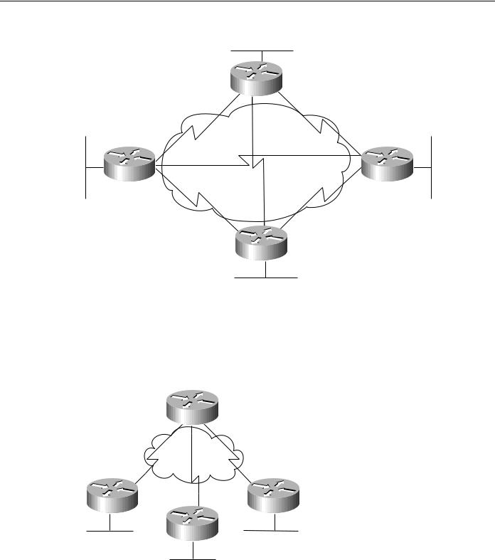
The fully meshed configuration (see Figure 10-3) is recommended only for very small DDR networks. Fully meshed topologies can streamline the dialing process for any-to-any connectivity as each site can call any other site directly, rather than having to call through a central site, which then places another call to the target site. However, the configuration for each site is more complex because each site must have mapping information for every other site.
If load sharing is desired, interfaces can be configured for MultiLink PPP capability. In addition to the complexity of the configuration, either sufficient interfaces must be available on each device to deal with the possibility of all of the other devices calling in, or the possibility of contention for interfaces needs to be understood and dealt with.
Designing DDR Internetworks 10-3
Traffic and Topology of DDR
Figure 10-3 Fully meshed topology
Router A
Router D |
Router B |
Router C
Hub-and-Spoke DDR Solutions
In a hub-and-spoke topology (see Figure 10-4), a central site is connected to several remote sites. The remote sites communicate with the central site directly; they do not call any of the other remote sites. This topology works very well for scaling large solutions.
Figure 10-4 Hub-and-spoke topology.
Router A
Router B |
Router D |
Router C
Hub-and-spoke topologies are easier to configure than fully meshed topologies when multipoint topologies are required because remote site dialer interfaces are mapped only to the central site. This allows most of the design complexity (such as addressing, routing, and authentication) to be managed on the DDR Hub. Configuration support of the remote sites can be greatly simplified (similar to one end of a point-to-point topology).
10-4 Cisco CCIE Fundamentals: Network Design

Traffic Analysis
If any-to-any connectivity initiation is required between remote sites, routing behavior may need to be modified depending on dialer interface behavior (that is, it may be necessary to disable split-horizon on distance vector routing protocols).
Multiple hubs can be used to provide further scaling of hub-and-spoke technologies. When using MultiLink PPP, as is very common in ISDN solutions, designers can implement Cisco IOS MultiChassis MultiLink PPP to scale the dial-in rotary group between multiple Network Access Servers. MultiChassis MultiLink PPP (MMP) is discussed further in Chapter 11, “Designing ISDN Internetworks,” in the section “Designing ISDN Internetworks.”
Traffic Analysis
For traffic analysis, develop a chart of which protocols need to be able to support DDR-based dialing from which devices. This will form the basis of the rest of the DDR design.
For example, Company KDT has selected a hub-and-spoke topology (to provide for scaling) and has developed the needs shown in Table 10-1 for its DDR cloud requirements.
Table 10-1 |
DDR Protocol Connectivity Requirements for KDT |
|
|
|
|
|
|
Remote Site |
Dial-In Protocols |
Dial-Out Protocols |
Notes |
|
|
|
|
c700A |
IP, IPX |
None |
|
|
|
|
|
c700B |
IP |
None |
|
|
|
|
|
c1600A |
IP, AppleTalk |
IP |
|
|
|
|
|
c2500A |
IP, IPX, AppleTalk |
IP, IPX, AppleTalk |
|
|
|
|
|
c2500B |
IP, IPX |
IP |
|
|
|
|
|
NAS3600A |
IP, IPX, AppleTalk |
IP, IPX, AppleTalk |
|
|
|
|
|
The purpose of Table is to identify which sites and protocols require the capability to initiate the DDR connections. Once connectivity is established, each protocol requires two-way connectivity via routing tables and dialer cloud address mapping. Dial-in versus dial-out is from the perspective of the hub.
Often a primary goal of a DDR network is to offer a cost improvement over WAN charges associated with dedicated connections. Additional traffic analysis must be performed for each protocol at this or the Dialer Filtering design stage. Network applications use the infrastructure provided by the internetwork in many different and often unexpected ways. It is critical to perform a thorough analysis of real-world network traffic that will transit the dialer media in order to determine whether a DDR network can operate in a feasible manner. Packet capture and analysis tools provide the most valuable tool for this analysis.
Dialer Interfaces
Access to the dialer media is via Cisco ISO Dialer interfaces. ISDN B channels, Synchronous Serial interfaces, and Asynchronous interfaces can all be converted to dialer interfaces using dialer interface configuration commands. To understand dialer interfaces, the following concepts are covered:
•
•
•
Supported physical interfaces
Dialer rotary groups
Dialer profiles
Designing DDR Internetworks 10-5

Dialer Interfaces
•
•
Dialer addressing
Dialer mapping
Dialer Interfaces also provide the basis for support of routing table spoofing and dialer filtering. This section focuses on lower-layer characteristics of dialer interfaces.
Supported Physical Interfaces
Several types of physical interfaces can be enabled as dialer interfaces.
Synchronous Serial Interfaces
Dialing on synchronous serial lines can be initiated using V.25bis dialing or DTR dialing. V.25bis is the ITU standard for in-band dialing. With in-band dialing, dialing information is sent over the same connection that carries the data. V.25bis is used with a variety of devices, including synchronous modems, ISDN terminal adapters (TAs), and Switched 56 DSU/CSUs.
With DTR dialing, the DTR signal on the physical interface is activated, which causes some devices to dial a number configured into that device.When using DTR dialing, the interface cannot receive calls. But using DTR dialing allows lower-cost devices to be used in cases where only a single number needs to be dialed. Synchronous Serial Lines support PPP, HDLC, and X.25 datagram encapsulation.
To convert a synchronous serial interface into a dialer interface, use the Cisco IOS command dialer in-band or dialer dtr.
ISDN Interfaces
All ISDN devices subscribe to services provided by an ISDN service provider, usually a telephone company. ISDN DDR connections are made on B channels at 56 or 64 Kbps depending on the bearer capabilities of the end-to-end ISDN switching fabric. MultiLink PPP is often used to allow BRI devices to aggregate both B channels for great bandwidth and throughput. See Chapter 11, “Designing ISDN Internetworks,” for guidance when designing ISDN internetworks.
ISDN BRI and PRI interfaces are automatically configured as dialer in-band interfaces. ISDN can support PPP, HDLC, X.25, and V.120 encapsulation. Typically, PPP will be used for DDR solutions. ISDN interfaces are automatically configured as dialer in-band interfaces.
For example, when examining a BRI interface on a Cisco IOS router, you can see that it is in the spoofing (pretending to be up/up so the routing table can point to this interface):
c1600A#sh int bri 0
BRI0 is up, line protocol is up (spoofing)
However, the physical interfaces are the individual B (BRI0:1 and BRI0:2) channels being managed by the dialer interface (BRI0).
c1600A#sh int bri 0 1
BRI0:1 is down, line protocol is down Hardware is BRI
MTU 1500 bytes, BW 64 Kbit, DLY 20000 usec, rely 255/255, load 1/255 Encapsulation PPP, loopback not set, keepalive set (10 sec)
LCP Closed, multilink Closed Closed: IPCP, CDPCP
10-6 Cisco CCIE Fundamentals: Network Design

Dialer Rotary Groups
Asynchronous Modem Connections
Asynchronous connections are used by communication servers or through the auxiliary port on a router. Asynchronous DDR connections can be used to support multiple network layer protocols. When considering asynchronous DDR solutions, designers should consider if the internetworking applications can tolerate the longer call setup time and lower throughput of analog modems (in comparison with ISDN). For some design applications, DDR over asynchronous modem connections may provide a very cost-effective option.
In order to dial out using asynchronous connections, chat scripts must be configured so that modem dialing and login commands are sent to remote systems. For design flexibility, multiple chat scripts can be configured on dialer maps. Modem scripts can be used to configure modems for outbound calls. Login scripts are intended to deal with logging onto remote systems and preparing the link for establishment of PPP. Chat scripts are configured with expect-send pairs and keywords to modify settings, as follows:
chat-script dialnum "" "atdt\T" TIMEOUT 60 CONNECT \c
If you are using asynchronous DDR and calling a system that requires a character-mode login, use the system-script keyword with the dialer map command.
Chat scripts often encounter problems with timing due to the fact that they are run with much greater precision than when a human is controlling the connection. For example, sometimes when a modem sends the CONNECT message, it is not actually ready to send data, and may even disconnect if any data is received on the TX circuitry. To avoid such failure modes, pauses are added at the head of some send strings.
Each send string is terminated with a carriage return, even when it’s a null string (“”). Often the chat script will be set up without the final “send” string. This may produce unexpected results. Ensure that all chat scripts have complete expect-send pairs. If the final element in the chat script logic turns out to be an expect (as in the previous example), use the \c as the final send to suppress unwanted output.
Use the debug chat commands to troubleshoot chat script problems. Line-specific debugging can provide additional details when expect-send logic is failing.
Dialer Rotary Groups
For hub-and-spoke or fully meshed topologies that support multiple connections between sites, physical interfaces can be grouped into rotary groups with the dialer rotary-group command. Physical interfaces assigned to the dialer rotary-group inherit their configuration from the corresponding interface dialer.
If one of the physical interfaces in a rotary group is busy, the next available interface can be used to place or receive a call. It is not necessary to configure rotary groups for BRI or PRI interfaces as ISDN B channels are automatically placed into a rotary-group, however multiple BRI or PRI interfaces can be grouped using dialer rotary-group.
Dialer Profiles
Dialer profiles introduced in Cisco IOS 11.2 offer additional design flexibility such as multisite bridging over ISDN. Dialer profiles provide an alternative methodology for designing DDR networks by removing the logical definition of dialer sites from the physical dialer interfaces.
Designing DDR Internetworks 10-7

Dialer Interfaces
Encapsulation Methods
When a clear DataLink is established between two DDR peers, internetworking datagrams must be encapsulated and framed for transport across the Dialer media. The encapsulation methods available depend on the physical interface being used. Cisco supports Point-to-Point Protocol (PPP), High-Level Data Link Control (HDLC), Serial Line Interface Protocol (SLIP), and X.25 data-link encapsulations for DDR:
•PPP is the recommended encapsulation method because it supports multiple protocols and is used for synchronous, asynchronous, or ISDN connections. In addition, PPP performs address negotiation and authentication and is interoperable with different vendors.
•HDLC is supported on synchronous serial lines and ISDN connections only. HDLC supports multiple protocols. However, HDLC does not provide authentication, which may be required if using dialer rotary groups.
•SLIP works on asynchronous interfaces only and is supported by IP only. Addresses must be configured manually. SLIP does not provide authentication and is interoperable only with other vendors that use SLIP.
•X.25 is supported on synchronous serial lines and a single ISDN B channel.
Addressing Dialer Clouds
There are two ways of setting up addressing on dialer clouds, as follows:
•Applying a subnet to the dialer cloud
Each site connected to the dialer cloud is given a unique node address on a shared subnet for use on its dialer interface. This method is similar to numbering a LAN or multipoint WAN and simplifies the addressing scheme and creation of static routes.
•Using unnumbered interfaces
Similar to using unnumbered addressing on leased line point-to-point interfaces, the address of another interface on the router is borrowed for use on the dialer interface. Unnumbered addressing takes advantage of the fact that there are only two devices on the point-to-point link. The routing table points to an interface (the dialer interface) and a next-hop address (which must match a dialer map: static or dynamic).
Building static routes for unnumbered interfaces can be a little more complex because the router must be configured with the interface that finds the next-hop out.
Dialer Maps
Similar to the function provided by an ARP table, dialer map statements translate next-hop protocol addresses to telephone numbers. Without statically configured dialer maps, DDR call initiation cannot occur. When the routing table points at a dialer interface, and the next-hop address is not found in a dialer map, the packet is dropped.
In the following example, packets received for a host on network 172.20.0.0 are routed to a next-hop address of 172.20.1.2, which is statically mapped to telephone number 555-1212:
interface dialer 1
ip address 172.20.1.1 255.255.255.0
dialer map ip 172.20.1.2 name c700A 5551212
!
ip route 172.20.0.0 255.255.255.0 172.20.1.2
10-8 Cisco CCIE Fundamentals: Network Design