
- •Главная
- •1.1 Напряжений и концентраторы
- •1.1.3 Концентраторы напряжения
- •1.3 Stress concentration factor
- •1.7 Elastic-plastic stress concentration
- •1.8 Joints: bolts and welds
- •3. Механические свойства конструкционных материалов
- •3.1 Напряженности испытания
- •3.2 Stress - strain diagram
- •3.3 Testing schemes
- •3.4 Strength
- •4 Прочность материалов
- •4.1 Tension and compression
- •4.2 Shear and torsion
- •4.3 Stress-strain state
- •4.4 Bending: force and moment diagrams
- •4.5 Geometrical characteristics of sections
- •4.6 Bending: stress and deformation
- •4.7 Mixed mode loading
- •4.8 Buckling
- •4.9 Statically indeterminate systems
- •4.10 Three-dimensional structures
- •References
- •5. Theory of elasticity
- •5.1 Deformation
- •5.2 Stress
- •5.3 Hooke's law
- •5.4 Plane problems
- •5.5 Torsion
- •5.6 Bending
- •5.7 Polar coordinates
- •5.8 Plates
- •5.9 Shells
- •5.10 Contact stresses
- •6.2 Distribution functions
- •6.3 Structural models of reliability
- •6.4 Limiting state
- •6.5 Dispersion
- •6.6 Durabilty
- •6.7 Design by reliability criterion
- •6.8 Risk
- •6.9 Safety classes
- •6.10 Risk : structural and social
- •References
- •7 Materials science
- •7.1 Crystalline solids
- •7.2 Mechanical properties
- •7.3 Failure
- •7.4 Phase diagrams
- •7.5 Heat treatment of metals and alloys
- •7.6 Corrosion of metals and alloys
- •7.7 Casting
- •7.8 Polymers
- •7.9 Composites
- •7.10 Forming of metals
- •8.2 Mechanical properties
- •8.3 Stress concentration
- •8.4 Defects
- •8.5 Residual Stress
- •8.6 Strength
- •8.7 Fatigue strength
- •8.8 Fracture
- •8.9 Weldability
- •References
- •9 Composites
- •9.1 Structure of composites
- •9.2 Fibers
- •9.3 Rigidity
- •9.4 Strength
- •9.5 Crack resistance
- •9.6 Optimization
- •9.7 Fatigue and temperature effect
- •9.8 Reliability
- •9.9 Joints
- •9.10 Material selection
- •References
- •10 Finite element analysis
- •10.1 Finite element method
- •10.2 Finite elements
- •10.3 Meshing
- •10.4 Boundary conditions
- •10.5 Deformation
- •10.6 Accuracy
- •10.7 Heat transfer analysis
- •10.8 Dynamics
- •10.9 Computational fluid dynamics
- •10.10 Design analysis
- •References
References
M. Gere, S.P.Timoshenko Mechanics of Materials, 4th edition, Pws Pub Co, 1997.
F. B. Seely, Advanced Mechanics of Materials, John Wiley and Sons, Inc., New York, 1952.
L. Spiegel, G. Limbrunner Applied Statics and Strength of Materials, 3rd edition, Prentice-Hall Career & Technology, 1999.
S. Timoshenko Strength of Materials, Part I & II, Van Nostrand Company, Princeton, N. J., 1956.
THEMES
Theme 1. Stress Concentration Theme 2. Fracure Mechanics Theme 3. Mechanical Properties Theme 4. Strength of Materials Theme 5. Theory of Elasticity Theme 6. Structural Safety Theme 7. Material Science Theme 8. Welds Theme 9.Composite Materials Theme 10. Finite Element Analysis
5. Theory of elasticity
Igor Kokcharov and Igor Zyryanov
5.1 Deformation
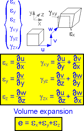 An
elastic body can be shifted and extended. Analysis of the
displacements u, v and w shows whether there is deformation or not.
Change of the element sizes and its shape can be characterized by
deformation, difference in displacements, or by strain. Strain is the
deformation of an element divided by the original length of the
element. There are 6 components of strain. There is linear strain ei
and shear strain gij
. The strain ex
is the derivative of displacement u with respect to coordinate x.
Definitions for the other strain components are shown in the
figure.
Volume expansion e depends on linear components of
strain only. Shear strain gxy
has no affect on the parameter.
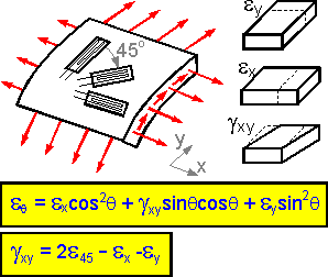 The
strain components change if the axes is rotated by angle q. According
to the second formula shown at the right, shear strain gxy
= 0 if all three linear components of strain are equal.
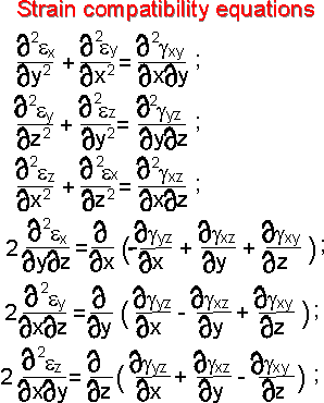 In
an elastic body strains cannot be chosen arbitrarily, they must
satisfy to the strain compatibility equations.
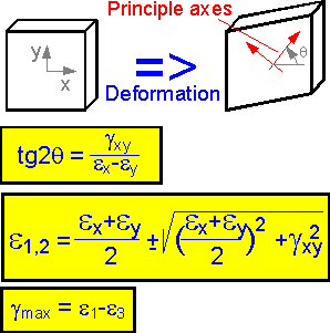 For
plane strain there are two axes along which the linear strains are at
a maximum. The axes are called principle axes. Angle q defines their
position. The expressions are given for maximum linear strains e1,
e2
(plane problem) and maximum shear strain gmax (three-dimensional
problem).
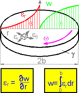 The
radial displacement w is smaller in the center of rotating disk. The
displacement is a result of summation under the shown curve of radial
strain er.
The larger radial strain and gradient of the displacement are
observed in the central part of the disk.
The
radial displacement w is smaller in the center of rotating disk. The
displacement is a result of summation under the shown curve of radial
strain er.
The larger radial strain and gradient of the displacement are
observed in the central part of the disk.
5.2 Stress
 Stress
is the intensity of an internal force acting on a point in an object.
Stress is measured in units of force per area. Axial (or normal)
stress (s) is defined as the force perpendicular to the cross
sectional area of the body divided by the cross sectional area. Shear
stress (t) acts parallel to an imaginary plane cut through an
object.
Centrifugal forces act to move an elementary ring
from center. The elementary ring is extended. Both shown stress
components, radial and tangential, are positive.
Stress
is the intensity of an internal force acting on a point in an object.
Stress is measured in units of force per area. Axial (or normal)
stress (s) is defined as the force perpendicular to the cross
sectional area of the body divided by the cross sectional area. Shear
stress (t) acts parallel to an imaginary plane cut through an
object.
Centrifugal forces act to move an elementary ring
from center. The elementary ring is extended. Both shown stress
components, radial and tangential, are positive.
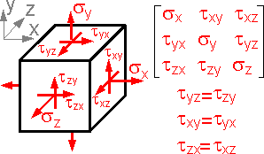 There
are 9 stress components at any point.
The condition for zero
rotation of the element, found by taking moments about the axes
through the center of the cube parallel to the coordinate axes,
reduces the number of independent components to six.
Six stress
components are enough to describe any state of stress in a
point.
 The
equilibrium equations must be satisfied for an elastic body. Mass is
not considered in the equations. The shown stress components
correspond to three-point bending and satisfy the equilibrium
equations.
 The
cut element must be in equilibrium. This requirement helps find the
stresses at the incline planes. The sum of the forces at axis x equal
to zero. Force is equal to stress * area.
The formula
gives the expression for principle stresses - normal maximum stresses
at incline planes at a point in plane stress state.
The
cut element must be in equilibrium. This requirement helps find the
stresses at the incline planes. The sum of the forces at axis x equal
to zero. Force is equal to stress * area.
The formula
gives the expression for principle stresses - normal maximum stresses
at incline planes at a point in plane stress state.
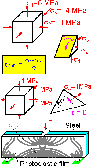 The
shown normal stresses are principle because there are no shear
stresses at the planes. The maximum shear stress acts at an incline
plane between maximum and minimum principle stresses s1
and s3.
Maximum shear stress, tmax
= (6-(-4))/2 = 5 MPa.
For all around tension where the
three principle stresses are equal there is no shear stress at any
incline planes. All rectangular coordinate sets can be considered the
principle ones. The normal stress at any incline plane is also equal
to 1 MPa.
The fringe pattern in the photoelastic film
shows lines of equal shear stress tmax.
Maximum shear stress is equal to one-half the maximum tensile stress.
The picture illustrates the regions of high stress (density of the
fringes).
The
shown normal stresses are principle because there are no shear
stresses at the planes. The maximum shear stress acts at an incline
plane between maximum and minimum principle stresses s1
and s3.
Maximum shear stress, tmax
= (6-(-4))/2 = 5 MPa.
For all around tension where the
three principle stresses are equal there is no shear stress at any
incline planes. All rectangular coordinate sets can be considered the
principle ones. The normal stress at any incline plane is also equal
to 1 MPa.
The fringe pattern in the photoelastic film
shows lines of equal shear stress tmax.
Maximum shear stress is equal to one-half the maximum tensile stress.
The picture illustrates the regions of high stress (density of the
fringes).
