
- •Главная
- •1.1 Напряжений и концентраторы
- •1.1.3 Концентраторы напряжения
- •1.3 Stress concentration factor
- •1.7 Elastic-plastic stress concentration
- •1.8 Joints: bolts and welds
- •3. Механические свойства конструкционных материалов
- •3.1 Напряженности испытания
- •3.2 Stress - strain diagram
- •3.3 Testing schemes
- •3.4 Strength
- •4 Прочность материалов
- •4.1 Tension and compression
- •4.2 Shear and torsion
- •4.3 Stress-strain state
- •4.4 Bending: force and moment diagrams
- •4.5 Geometrical characteristics of sections
- •4.6 Bending: stress and deformation
- •4.7 Mixed mode loading
- •4.8 Buckling
- •4.9 Statically indeterminate systems
- •4.10 Three-dimensional structures
- •References
- •5. Theory of elasticity
- •5.1 Deformation
- •5.2 Stress
- •5.3 Hooke's law
- •5.4 Plane problems
- •5.5 Torsion
- •5.6 Bending
- •5.7 Polar coordinates
- •5.8 Plates
- •5.9 Shells
- •5.10 Contact stresses
- •6.2 Distribution functions
- •6.3 Structural models of reliability
- •6.4 Limiting state
- •6.5 Dispersion
- •6.6 Durabilty
- •6.7 Design by reliability criterion
- •6.8 Risk
- •6.9 Safety classes
- •6.10 Risk : structural and social
- •References
- •7 Materials science
- •7.1 Crystalline solids
- •7.2 Mechanical properties
- •7.3 Failure
- •7.4 Phase diagrams
- •7.5 Heat treatment of metals and alloys
- •7.6 Corrosion of metals and alloys
- •7.7 Casting
- •7.8 Polymers
- •7.9 Composites
- •7.10 Forming of metals
- •8.2 Mechanical properties
- •8.3 Stress concentration
- •8.4 Defects
- •8.5 Residual Stress
- •8.6 Strength
- •8.7 Fatigue strength
- •8.8 Fracture
- •8.9 Weldability
- •References
- •9 Composites
- •9.1 Structure of composites
- •9.2 Fibers
- •9.3 Rigidity
- •9.4 Strength
- •9.5 Crack resistance
- •9.6 Optimization
- •9.7 Fatigue and temperature effect
- •9.8 Reliability
- •9.9 Joints
- •9.10 Material selection
- •References
- •10 Finite element analysis
- •10.1 Finite element method
- •10.2 Finite elements
- •10.3 Meshing
- •10.4 Boundary conditions
- •10.5 Deformation
- •10.6 Accuracy
- •10.7 Heat transfer analysis
- •10.8 Dynamics
- •10.9 Computational fluid dynamics
- •10.10 Design analysis
- •References
8.9 Weldability
 Weldability
is the ability of materials (or structures) to form a strong
defect-free weld. Poor weldability results in hot cracking, cold
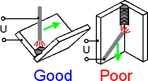
cracking or lack of fusion. Preliminary heating of base parts
(preheating) decreases hot cracking. The best weldability can be
obtained in the gravity position. Weldability depends on materials.
This list is in order of decreasing weldability:
Steel
0.2%C, cold-rolled
Stainless steel
Aluminum alloy 7075-T6
Ductile iron
The melting points of aluminum alloy
and steel differ by more than 500 degrees Celsius. The metals cannot
be melted together.
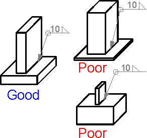 To
form a defect-free tee-joint it is better to use similar thickness of
welded parts. An all-around welding of two massive (rigid) parts
results in hot cracking.
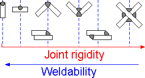 The
more rigid a welded structure, the more susceptible to hot cracking.
The specimens are shown in increasing order for susceptibility to hot
cracking and decreasing order of weldability.
The
more rigid a welded structure, the more susceptible to hot cracking.
The specimens are shown in increasing order for susceptibility to hot
cracking and decreasing order of weldability.
 There
are special tests to estimate weldability of materials:
1.
Y-groove restrain cracking test for heavy plates with a new weld in
the center. Hot cracking in the new weld is under investigation. This
test helps to estimate susceptibility to hot cracking.
2.The
implant method for studying weldability and determining
susceptibility to cold cracking.
3.Tension of a machined
specimen for studying susceptibility to lamellar cracking.
8.1
There
are some simple rules how to design a reliable welded structure. We
mention a few of them here:
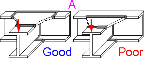 A.
Keep welds away from zones of high stress concentration.
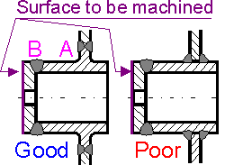 B.
Keep welds away from surfaces to be machined.
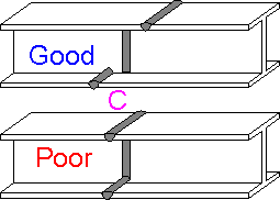
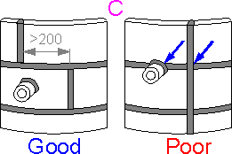 C.
Don't make butt-weld intersections.
 D.
Place vertical walls where force is applied.
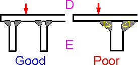 E.
Choose proper weld size.
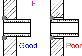 F.
Avoid gaps.
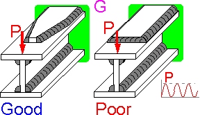 G.
Don't use sharp rigidity transition in tensile flange.
References
Cary, H.B. Modern Welding Technology, Englewood Cliffs, N.J.: Prentice-Hall, 1979.
Gray, T.G.F., J. Spence, and T.H. North Rational Welding Design, New York : Butterworths, 1975.
Kalpakjian S. Manufacturing Engineering And Technology, Addison-Wesley Publishing Company, 1989.
Metals Handbook, 9th ed., Vol. 6: Welding, Brazing, and Soldering, Metals Park, Ohio: American Society for Metals, 1983.
Welding Handbook 8th ed., 3 vols, Maiami: American Welding Society, 1987.
THEMES
Theme 1. Stress Concentration Theme 2. Fracure Mechanics Theme 3. Mechanical Properties Theme 4. Strength of Materials Theme 5. Theory of Elasticity Theme 6. Structural Safety Theme 7. Material Science Theme 8. Welds Theme 9.Composite Materials Theme 10. Finite Element Analysis
9 Composites
Igor Kokcharov
9.1 Structure of composites
 A
composite material consists of two or more components. The components
have different mechanical properties.
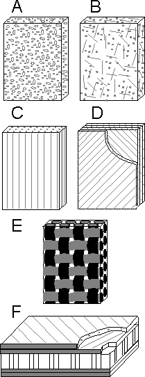
There are the
following types of composites:
A. composites reinforced by
particles;
B. composites reinforced by chopped strands;
C.
unidirectional composites;
D. laminates;
E. fabric
reinforced plastics;
F. honeycomb composite
structure;
A
composite material consists of two or more components. The components
have different mechanical properties.
There are the
following types of composites:
A. composites reinforced by
particles;
B. composites reinforced by chopped strands;
C.
unidirectional composites;
D. laminates;
E. fabric
reinforced plastics;
F. honeycomb composite
structure;
 Composite
materials are widely used in aerospace structures, passenger
airplanes, cars, and sporting goods.
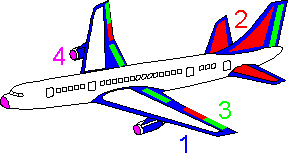
Use of aramid fiber
reinforced plastics 1, carbon fiber reinforced plastics 2, hybrid
fiber (aramid + carbon) reinforced plastics 3, and glass fiber
reinforced plastics 4 decreases the weight of passenger
airplanes.
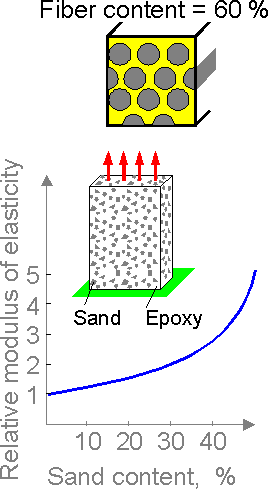 Particle
content is defined by studying the cross section of a specimen. The
parameter is equal to the ratio of the total area of the particles
(fibers) to the cross sectional area of the specimen.
Regarding
particle and fiber reinforced matrices, the modulus of elasticity
will increase with larger hard particle content.
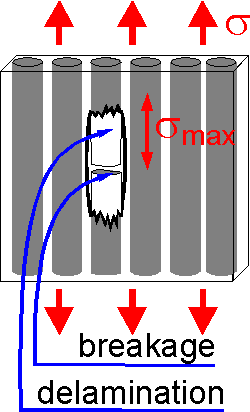 Broken
rigid fibers in a flexible matrix causes a stress concentration in
the neighboring fibers. The stress concentration factor increases
with the difference between the modulus of elasticity of the matrix
and fiber. It can range from 1.2 to 1.5.
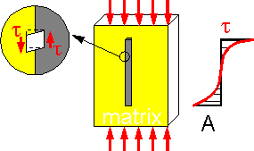 There
are shear stress concentrations at the bond surface between
components.
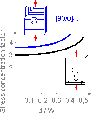 Stress
concentration in laminate materials is higher than in isotropic
materials. Hence, the strength of a notched composite specimen is
rather high.
The notation [0o/90o]2S
means the laminate is assembled with two layers oriented at 0o
and 90o.
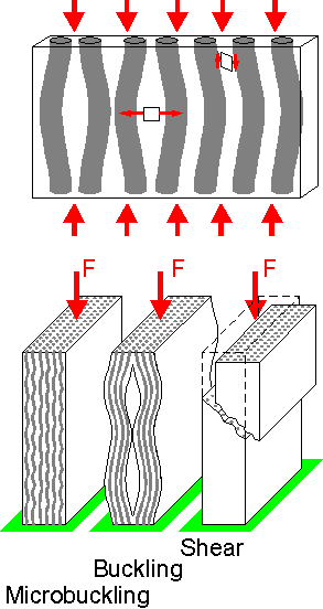 Tensile
and shear stresses cause different failure scenarios for composite
structures.
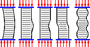 Honeycomb
composite structure has high flexural strength. Mechanisms of
stability loss under compression depends on many factors such as
adhesive quality, size of honeycomb, fiber filament, etc.
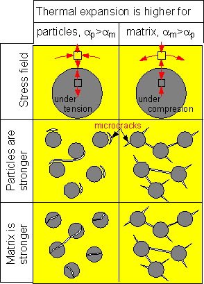 There
is a residual technological microcracking in composites reinforced by
particles. If thermal expansion is high for particles, then the
particles are under compression after cooling. Weak particles contain
internal microcracks. If the matrix or bond border is weaker than
particles, there are tangential microcracks in the matrix and at the
border.
