

5.5 Torsion
 Torsion
is related to shear stress. Only two shear stresses are nonzero at
planes perpendicular to the shaft axis. All other stress components
including all normal stresses in the chosen coordinate axes are equal
to zero.
There is no tensile strain in the vertical or
horizontal directions for pure shear (torsion). There are no readings
on the two strain gauges shown.
Torsion
is related to shear stress. Only two shear stresses are nonzero at
planes perpendicular to the shaft axis. All other stress components
including all normal stresses in the chosen coordinate axes are equal
to zero.
There is no tensile strain in the vertical or
horizontal directions for pure shear (torsion). There are no readings
on the two strain gauges shown.
 The
figure shows the results of a finite element analysis for a prismatic
bar under torsion. The shear deformation is at a maximum in the
center of the bar. The shape of the square mesh at the surface of the
bar changes. The height of the rhombus and its area become smaller.
This means that the bar becomes a little shorter.
The
figure shows the results of a finite element analysis for a prismatic
bar under torsion. The shear deformation is at a maximum in the
center of the bar. The shape of the square mesh at the surface of the
bar changes. The height of the rhombus and its area become smaller.
This means that the bar becomes a little shorter.
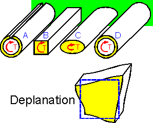 The
figure shows four specimens with equal cross sections. The
thin-walled example A demonstrates the smallest torsional
rigidity.
The specimens are shown in increasing order of the
torsional rigidity.
Deplanation of a plane section is the
out-of-plane deformation of its points. For all examples except
cylinder D there is deplanation.
The
figure shows four specimens with equal cross sections. The
thin-walled example A demonstrates the smallest torsional
rigidity.
The specimens are shown in increasing order of the
torsional rigidity.
Deplanation of a plane section is the
out-of-plane deformation of its points. For all examples except
cylinder D there is deplanation.
 Shear
stress is doubled near the small keyslot. The stress concentration
factor is equal to 2 for the small keyslot.
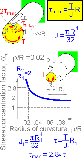
There is
stress concentration near the diameter change. The stress
concentration factor depends on radius of curvature.
Shear
stress is doubled near the small keyslot. The stress concentration
factor is equal to 2 for the small keyslot.
There is
stress concentration near the diameter change. The stress
concentration factor depends on radius of curvature.
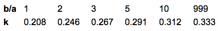
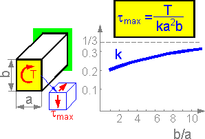 The
formula defines maximum shear stress for a rectangular section. The
maximum shear stress acts at the middle of the longer edge of the
rectangle. The coefficient k grows from 0.208 at b/a=1 to 0.333 at
infinity.
The
formula defines maximum shear stress for a rectangular section. The
maximum shear stress acts at the middle of the longer edge of the
rectangle. The coefficient k grows from 0.208 at b/a=1 to 0.333 at
infinity.
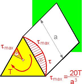 Maximum
shear stress in the middle of a side of a triangle is inversely
proportional to a3.
The shear stress is equal to zero in the corners and center.
Maximum
shear stress in the middle of a side of a triangle is inversely
proportional to a3.
The shear stress is equal to zero in the corners and center.
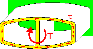 For
thin-walled symetrical sections the shear stress is approximately
zero in the inner wall. All shear stresses tend toward the "external
circle".
For
thin-walled symetrical sections the shear stress is approximately
zero in the inner wall. All shear stresses tend toward the "external
circle".
5.6 Bending
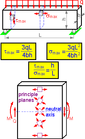 There
are shear and tensile stresses in bending beams. Usually the beams
fail due to bending tensile stress. An exception is beams with high
h/L ratio. A height increase results in an increase in the tmax/smax
ratio.
The shear stress is at a maximum and there is no
tensile bending stress at the neutral line of a bending beam. The
maximum tensile stress act at the upper or lower segments of the
beam.
The principle planes are planes where there are no
shear stresses and the normal stresses are at a maximum. The
principle axes are inclined by 45o
to the neutral axis. The principle axes coincide with the coordinate
axes at the upper and lower sections of a bending beam.
There
are shear and tensile stresses in bending beams. Usually the beams
fail due to bending tensile stress. An exception is beams with high
h/L ratio. A height increase results in an increase in the tmax/smax
ratio.
The shear stress is at a maximum and there is no
tensile bending stress at the neutral line of a bending beam. The
maximum tensile stress act at the upper or lower segments of the
beam.
The principle planes are planes where there are no
shear stresses and the normal stresses are at a maximum. The
principle axes are inclined by 45o
to the neutral axis. The principle axes coincide with the coordinate
axes at the upper and lower sections of a bending beam.
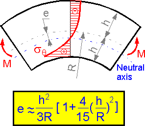 The
neutral line is shifted to the center for a curved beam. The absolute
value of the maximum compressive stress is smaller than that for
tension for the shown loading condition. For R/h > 20 the stress
field can be considered the same as for a straight beam.
The
neutral line is shifted to the center for a curved beam. The absolute
value of the maximum compressive stress is smaller than that for
tension for the shown loading condition. For R/h > 20 the stress
field can be considered the same as for a straight beam.
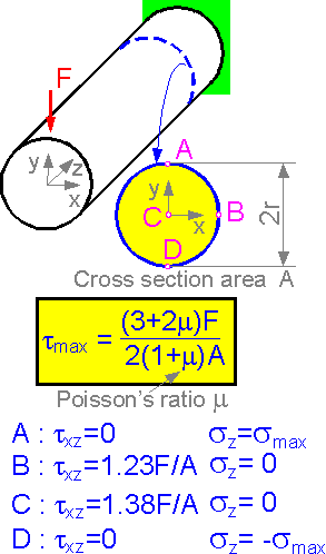 The
maximum shear stress depends on the transverse force F, the
cross-sectional area A and Poisson's ratio m. The shear stress is at
a maximum in the center of the section. The bigger the distance from
the neutral axis, the bigger the bending tensile stress.
The
maximum shear stress depends on the transverse force F, the
cross-sectional area A and Poisson's ratio m. The shear stress is at
a maximum in the center of the section. The bigger the distance from
the neutral axis, the bigger the bending tensile stress.
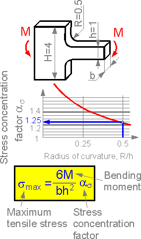 There
is a stress concentration in the bending beam. The stress
concentration factor depends on the ratio of the radius of curvature
to the decreased height of the beam.
There
is a stress concentration in the bending beam. The stress
concentration factor depends on the ratio of the radius of curvature
to the decreased height of the beam.
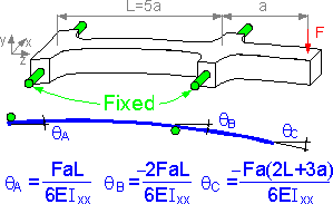 The
figure shows a curved central line of the beam. The angle of rotation
is at a maximum at the right edge of the beam.
The
figure shows a curved central line of the beam. The angle of rotation
is at a maximum at the right edge of the beam.
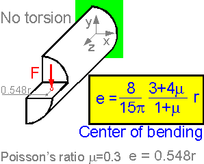 Shear
stress can result in torsion of non-symmetrical sections. Applying
force at a distance e=0.548r does not cause torsion of the beam with
a half-round cross section.
Shear
stress can result in torsion of non-symmetrical sections. Applying
force at a distance e=0.548r does not cause torsion of the beam with
a half-round cross section.