

7.4 Phase diagrams
 A
binary phase diagram is composed from the cooling curves of alloys
with various compositions. For an alloy with a particular composition
there are two points on the curve where a cooling rate is affected.
The first point corresponds to the temperature at which the alloy
begins to solidify. On the phase diagram this point belongs to the
Liquidus line. The second point corresponds to the temperature at
which the entire liquid has solidified. On the phase diagram this
point belongs to the Solidus line.
A
binary phase diagram is composed from the cooling curves of alloys
with various compositions. For an alloy with a particular composition
there are two points on the curve where a cooling rate is affected.
The first point corresponds to the temperature at which the alloy
begins to solidify. On the phase diagram this point belongs to the
Liquidus line. The second point corresponds to the temperature at
which the entire liquid has solidified. On the phase diagram this
point belongs to the Solidus line.
 This
diagram dispays the complete liquid and solid solubility of two
component otherwise known as a binary isomorphous system. This occurs
when the components have the same crystal structure and approximately
the same radii, electro negativity and valence. For instance, systems
of Ni-Cu and Ag-Au exhibit this type of diagram.
At the
temperature T1
for an alloy of 50%M + 50%N:
Composition of solid solution a is
determined at point c - 30%M +70%N.
Composition of Liquid is
determined at point a - 80%M +20%N.
% Liquid = bc/ac •
100% = (70-50)/(70-20) В·
100 % = 40%
% a = ab/ac •
100% = (50-20)/(70-20) В·
100 % = 60%
This
diagram dispays the complete liquid and solid solubility of two
component otherwise known as a binary isomorphous system. This occurs
when the components have the same crystal structure and approximately
the same radii, electro negativity and valence. For instance, systems
of Ni-Cu and Ag-Au exhibit this type of diagram.
At the
temperature T1
for an alloy of 50%M + 50%N:
Composition of solid solution a is
determined at point c - 30%M +70%N.
Composition of Liquid is
determined at point a - 80%M +20%N.
% Liquid = bc/ac •
100% = (70-50)/(70-20) В·
100 % = 40%
% a = ab/ac •
100% = (50-20)/(70-20) В·
100 % = 60%
 The
following diagram displays the complete liquid and limited solid
solubility of two components otherwise known as the binary eutectic
system. There are two solid phases (solid solutions): a - rich in the
component M and b - rich in the component N.
At point O
(Eutectic point) three phases (one liquid and two solid phases)
coexist simultaneously at the eutectic composition and
temperature.
The
following diagram displays the complete liquid and limited solid
solubility of two components otherwise known as the binary eutectic
system. There are two solid phases (solid solutions): a - rich in the
component M and b - rich in the component N.
At point O
(Eutectic point) three phases (one liquid and two solid phases)
coexist simultaneously at the eutectic composition and
temperature.
 Line
bd or the Solvus line protrays the change of the maximum
concentration of component M in component N. At the temperature T1
the maximum concentration M in N is 10%. The highest possible
solubility of the component M in component N (and vise verse) is
found at the eutectic temperature. On the diagram this constant
temperature line goes through the eutectic point O.
Line
bd or the Solvus line protrays the change of the maximum
concentration of component M in component N. At the temperature T1
the maximum concentration M in N is 10%. The highest possible
solubility of the component M in component N (and vise verse) is
found at the eutectic temperature. On the diagram this constant
temperature line goes through the eutectic point O.
 All
alloys with composition along line ab comprise the eutectic structure
which alternates layers of a and b phases. The closer the alloy to
the eutectic composition, the higher amount of the eutectic it
contains. The solidified alloys within line ab is a mixture of a
grains precipitated prior to the eutectic reaction and grains of the
eutectic. While the alloys on the right from point O - mixture of b
and the eutectic grains.
All
alloys with composition along line ab comprise the eutectic structure
which alternates layers of a and b phases. The closer the alloy to
the eutectic composition, the higher amount of the eutectic it
contains. The solidified alloys within line ab is a mixture of a
grains precipitated prior to the eutectic reaction and grains of the
eutectic. While the alloys on the right from point O - mixture of b
and the eutectic grains.
7.5 Heat treatment of metals and alloys
 Heat
treatment is a technological process involving the heating a metal
part, holding it at a certain temperature and then cooling it to room
temperature in order to attain desirable properties. The heating
temperature is varied depending on type of heat treatment and
material employed. The graph displays the temperature range of heat
treatment for steel.
Heat
treatment is a technological process involving the heating a metal
part, holding it at a certain temperature and then cooling it to room
temperature in order to attain desirable properties. The heating
temperature is varied depending on type of heat treatment and
material employed. The graph displays the temperature range of heat
treatment for steel.
 Tempering
is applied to quench hardened parts in order to reduce brittleness
and residual stress while increasing toughness. Additionally, the
hardness and strength are decreased while the ductility increases
with any increase of the tempering temperature.
Tempering
is applied to quench hardened parts in order to reduce brittleness
and residual stress while increasing toughness. Additionally, the
hardness and strength are decreased while the ductility increases
with any increase of the tempering temperature.
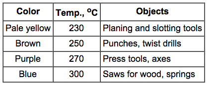 The
colors that appear on a steel surface as the result of oxidation also
differ with the temperature. The colors may be used as indicator to
attain desirable properties.
The
colors that appear on a steel surface as the result of oxidation also
differ with the temperature. The colors may be used as indicator to
attain desirable properties.
 In
plain carbon steel the maximum obtainable hardness is a function of
the carbon content. A higher hardness can be obtained by increasing
the carbon content. Cooling rate is an important parameter of
hardening. By increasing the cooling rate of steel the resultant
material becomes harder. The cooling rate depends on cooling medium
and also the size and geometry of the piece. The fastest cooling is
achieved using water, followed by oil and then air. Quenching
agitation restrains the formation of a vapor coating on the surface
of the piece in both water and oil and thus a higher cooling rate is
attained.
In
plain carbon steel the maximum obtainable hardness is a function of
the carbon content. A higher hardness can be obtained by increasing
the carbon content. Cooling rate is an important parameter of
hardening. By increasing the cooling rate of steel the resultant
material becomes harder. The cooling rate depends on cooling medium
and also the size and geometry of the piece. The fastest cooling is
achieved using water, followed by oil and then air. Quenching
agitation restrains the formation of a vapor coating on the surface
of the piece in both water and oil and thus a higher cooling rate is
attained.
 A
round bar quenched from one end will show varying hardness along its
length as the cooling rate changes. Hardenability describes the speed
of this transformation. The hardness of steel with a high
hardenability will change less rapid than that of steel with a low
hardenability.
The alloying of steels increases their
hardenability because the alloying elements permit more martensite to
form at a given cooling rate.
A
round bar quenched from one end will show varying hardness along its
length as the cooling rate changes. Hardenability describes the speed
of this transformation. The hardness of steel with a high
hardenability will change less rapid than that of steel with a low
hardenability.
The alloying of steels increases their
hardenability because the alloying elements permit more martensite to
form at a given cooling rate.
 Age
hardening involves three stages:
1. An alloy is heated above the
solvus line ab and held untill a homogeneous solid solution a is
obtained.
2. Rapid cooling the alloy to preserve supersaturated
solid solution.
3. Reheating the alloy to allow precipitation of
very small crystals of the b phase.
The age hardening of alloys
whose composition are located to the left of point a is impossible
due to the inability to form a supersaturated solid
solution.
Age
hardening involves three stages:
1. An alloy is heated above the
solvus line ab and held untill a homogeneous solid solution a is
obtained.
2. Rapid cooling the alloy to preserve supersaturated
solid solution.
3. Reheating the alloy to allow precipitation of
very small crystals of the b phase.
The age hardening of alloys
whose composition are located to the left of point a is impossible
due to the inability to form a supersaturated solid
solution.
 Annealing
is often used to soften a metal hardened through cold working in
order to allow consequent forming. By combining drawing and annealing
a fine wire can be drawn from a thick wire.
Annealing
is often used to soften a metal hardened through cold working in
order to allow consequent forming. By combining drawing and annealing
a fine wire can be drawn from a thick wire.