

5.7 Polar coordinates
 There
are tangential sq
and radial sr
stress components in polar coordinates. The coordinates are used for
round elastic bodies. The tangential tensile stress is at a maximum
at the inner surfaces of a cylindrical tube with inner pressure pi,
A.
The tangential stress is negative for external
pressure B.
There is no stress gradient if the external
and inner pressures are equal, C.
The eccentricity e
increases the maximum tensile stress at inner surface, D.
There
are tangential sq
and radial sr
stress components in polar coordinates. The coordinates are used for
round elastic bodies. The tangential tensile stress is at a maximum
at the inner surfaces of a cylindrical tube with inner pressure pi,
A.
The tangential stress is negative for external
pressure B.
There is no stress gradient if the external
and inner pressures are equal, C.
The eccentricity e
increases the maximum tensile stress at inner surface, D.
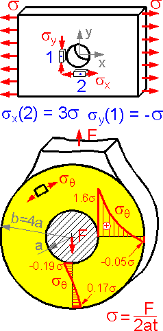 There
is a stress concentration near the round hole in the plate. The
stress concentration factor is equal to the ratio of the maximum to
the nominal stress. Stress concentration factor is 3.0 for point 2 .
Stress sy
is negative for point 1. Compression is similar to tension, merely
change the signs.
For the complex loading shown here, the
tangential stress sq is at a maximum in the horizontal section due to
the effect of "tension + bending + stress
concentration".
There
is a stress concentration near the round hole in the plate. The
stress concentration factor is equal to the ratio of the maximum to
the nominal stress. Stress concentration factor is 3.0 for point 2 .
Stress sy
is negative for point 1. Compression is similar to tension, merely
change the signs.
For the complex loading shown here, the
tangential stress sq is at a maximum in the horizontal section due to
the effect of "tension + bending + stress
concentration".
 Stress
concentration is higher for an elliptical hole under tension than for
a round hole.
For pure shear the absolute value of normal
stress is highest at a point between A and C. For a round hole (a=b)
the stress concentration factor is equal to 4 for pure shear.
The
stress pattern is linear for bending except near the elliptical hole
where stress increases.
Stress
concentration is higher for an elliptical hole under tension than for
a round hole.
For pure shear the absolute value of normal
stress is highest at a point between A and C. For a round hole (a=b)
the stress concentration factor is equal to 4 for pure shear.
The
stress pattern is linear for bending except near the elliptical hole
where stress increases.
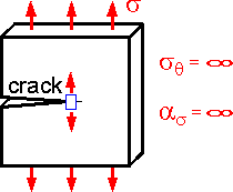 The
theoretical stress concentration factor for an ideal elastic body is
equal to infinity in the crack tip. Infinite stress is not seen in
actual materials due to plasticity and finite microstructure.
The
theoretical stress concentration factor for an ideal elastic body is
equal to infinity in the crack tip. Infinite stress is not seen in
actual materials due to plasticity and finite microstructure.
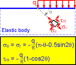 The
tangential stress is equal to the radial stress for this loading
scheme. The stress depends on angle q, not on the radius r. The
smaller the angle q, the larger the absolute value sq.
The stress is equal to distributed load q at the surface (q=0).
The
tangential stress is equal to the radial stress for this loading
scheme. The stress depends on angle q, not on the radius r. The
smaller the angle q, the larger the absolute value sq.
The stress is equal to distributed load q at the surface (q=0).
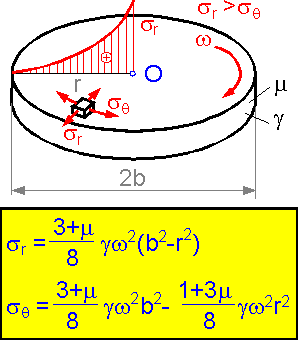 A
rotating disk: g is the density of material, m is Poisson's ratio, w
is the rotation speed.
The radial stress is higher than
the tangential stress. It is proportional to the squared rotation
speed and highest in the center.
A
rotating disk: g is the density of material, m is Poisson's ratio, w
is the rotation speed.
The radial stress is higher than
the tangential stress. It is proportional to the squared rotation
speed and highest in the center.
5.8 Plates
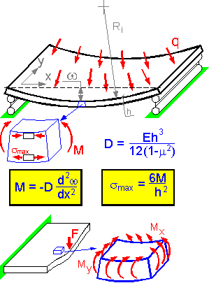 Bending
is the most important loading situation for thin plates. Bending
moment depends on bending rigidity D of the plate and the shape of
the deformed plate (deflection and its derivatives). The bigger the
thickness h, the bigger the bending rigidity D and the absolute value
of the bending moment. Maximum bending stress is proportional to
bending moment M and inversely proportional to h3.
There is usually bending relative to both axes x and y.
For the shown embedded thin plate, upper layers are under compression
and lower layers are under tension in the center of the plate.
Both
normal stress components sx
and sy
are at a maximum at the lower surface of the plate.
Bending
is the most important loading situation for thin plates. Bending
moment depends on bending rigidity D of the plate and the shape of
the deformed plate (deflection and its derivatives). The bigger the
thickness h, the bigger the bending rigidity D and the absolute value
of the bending moment. Maximum bending stress is proportional to
bending moment M and inversely proportional to h3.
There is usually bending relative to both axes x and y.
For the shown embedded thin plate, upper layers are under compression
and lower layers are under tension in the center of the plate.
Both
normal stress components sx
and sy
are at a maximum at the lower surface of the plate.
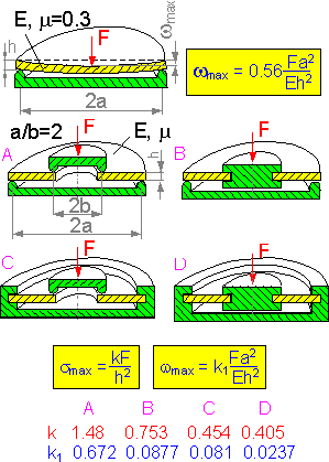 The
maximum deflection for a round simply supported plate with a force in
the center is proportional to (a/h)2.
The maximum stress and deflection depend on the support
method. The more rigid support, the smaller the maximum bending
stress smax
and maximum deflection of the round plate.
The
maximum deflection for a round simply supported plate with a force in
the center is proportional to (a/h)2.
The maximum stress and deflection depend on the support
method. The more rigid support, the smaller the maximum bending
stress smax
and maximum deflection of the round plate.
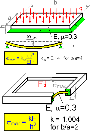 The
plate shown here is loaded with evenly distributed forces. The
maximum deflection in the center the of plate is inversely
proportional to h3.
Cutting the thickness h in half increases the deflection by 8
times.
For a rectangular plate with a force in the center,
the bending stress is at a maximum in the middle of the longer
side.
The
plate shown here is loaded with evenly distributed forces. The
maximum deflection in the center the of plate is inversely
proportional to h3.
Cutting the thickness h in half increases the deflection by 8
times.
For a rectangular plate with a force in the center,
the bending stress is at a maximum in the middle of the longer
side.
 The
stress concentration factor as is smaller for bending of thin plate
than for tension of a plate (as=3.0).
The stress concentration factor for bending depends on Poisson's
ratio m. It is approximately equal to 1.8 for steel (m=0.3).
The
stress concentration factor as is smaller for bending of thin plate
than for tension of a plate (as=3.0).
The stress concentration factor for bending depends on Poisson's
ratio m. It is approximately equal to 1.8 for steel (m=0.3).
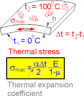 The
upper surface of the plate was rapidly heated to 100oC.
This causes thermal bending stress in the plate. The thermal stress
depends on the difference in temperatures, thermal expansion
coefficient and elastic constants of the material. The thermal stress
does not depends on the thickness h.
The
upper surface of the plate was rapidly heated to 100oC.
This causes thermal bending stress in the plate. The thermal stress
depends on the difference in temperatures, thermal expansion
coefficient and elastic constants of the material. The thermal stress
does not depends on the thickness h.